

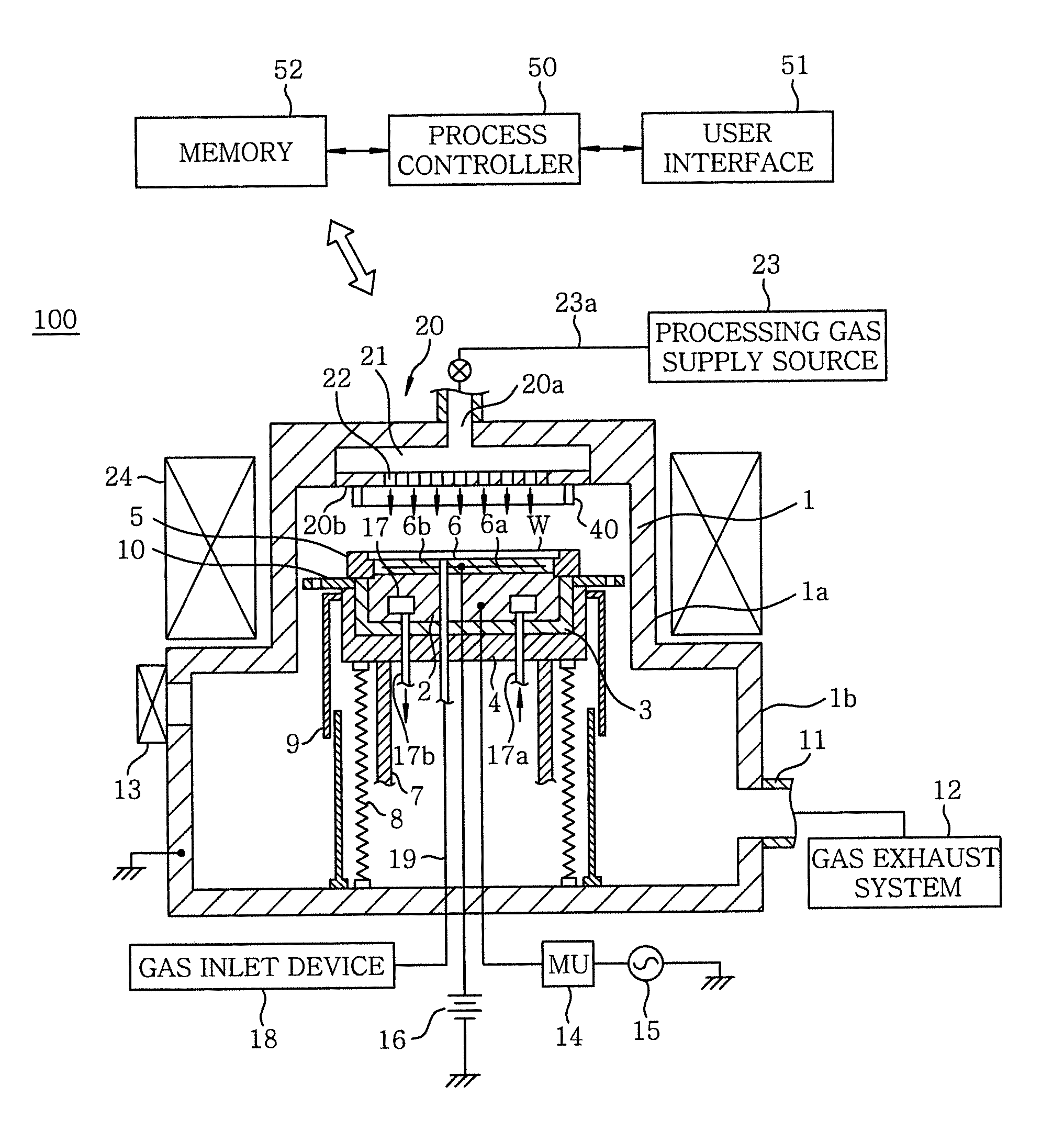
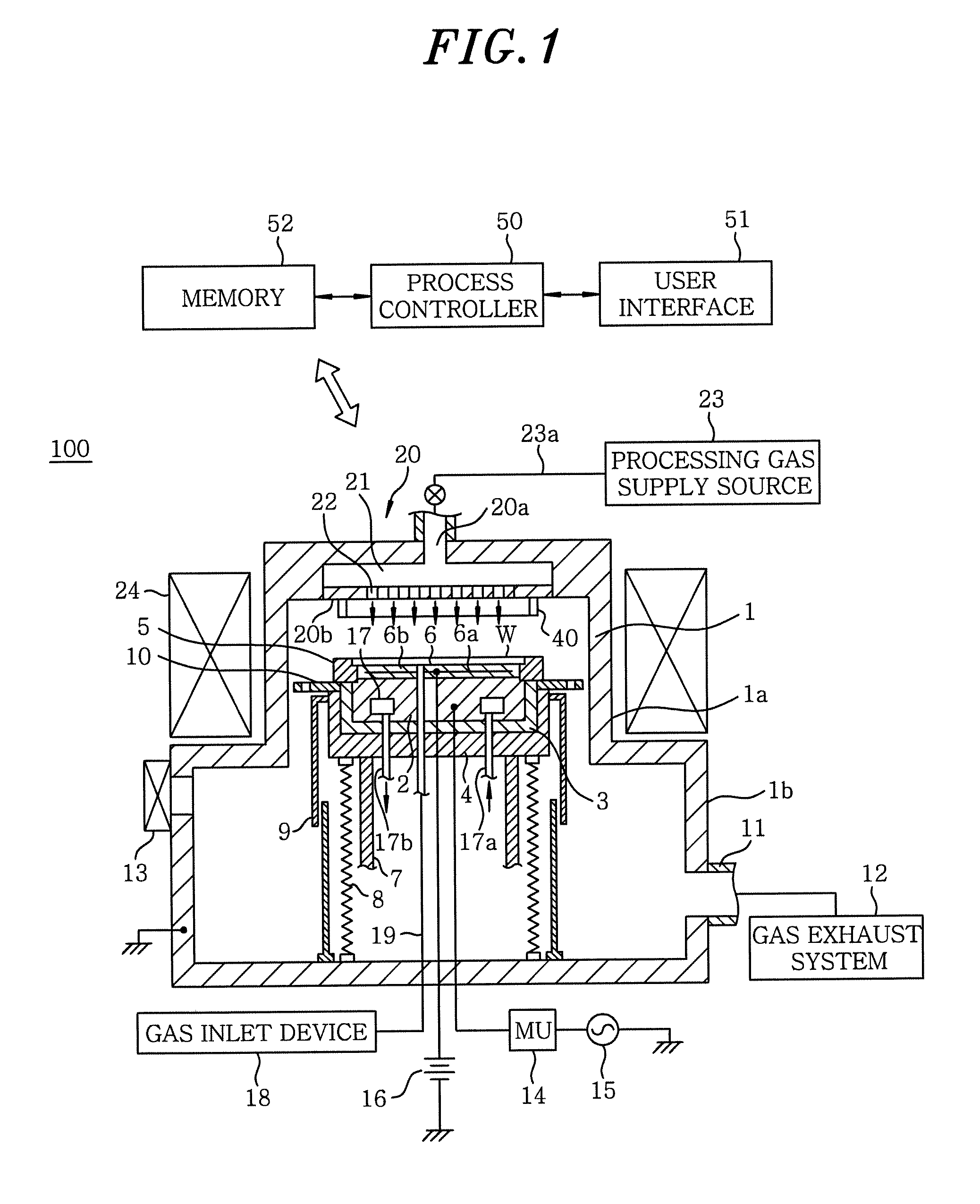
Plasma etching apparatus and method
a technology of etching apparatus and plasma, which is applied in the direction of instruments, computing, electric digital data processing, etc., can solve the problems of difficult control of etching profile, difficult to obtain uniform etching rate, etc., and achieve high integration of semiconductor devices and effective use
- Summary
- Abstract
- Description
- Claims
- Application Information
AI Technical Summary
Benefits of technology
Problems solved by technology
Method used
Image

Examples
experimental example 1
[0063]A plasma etching process was performed on the target object 110 having the structure of FIG. 6 by using the shower head 20 having the ring-shaped protrusion 40 of two sizes, A and B to be described below, thereby forming the hole 121 on the silicon substrate 101. A distance G (gap) between the upper and the lower electrode was set to be 22 mm, 27 mm and 32 mm. As for the shower head 20, one having an alumite treated surface was used.
[0064]Ring-shaped protrusion A:
[0065]Protruding amount H=15 mm
[0066]Outer diameter L1=260 mm
[0067]Inner diameter L2=240 mm
[0068]Width [(L1−L2)×½]=10 mm
[0069]Ring-shaped protrusion B:
[0070]Protruding amount H=21 mm
[0071]Outer diameter L1=270 mm
[0072]Inner diameter L2=240 mm
[0073]Width [(L1−L2)×½]=15 mm
[0074]The etching was performed under following conditions:
[0075]Resist: film thickness=7 μm
[0076]Processing gas: SF6 / O2=170 / 50 mL / min (sccm)
[0077]Pressure=37.3 Pa (280 mTorr)
[0078]RF frequency (high frequency power supply 15)=40 MHz
[0079]RF power=840 ...
experimental example 2
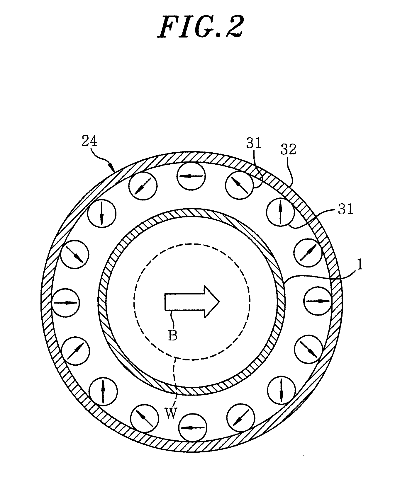
[0086]Under the same conditions as those of the experimental example 1, a plasma etching process was performed on the target object 110 having the structure of FIG. 6 by using the shower head 20 having 49 gas inlet openings 22 inclusively in an area S of about 108.7 mm2 in the central portion of the bottom surface 20b thereof while setting a distance (gap) G between the upper and the lower electrode at about 22 mm, 27 mm, 32 mm or 33 mm, thereby forming the hole 121 on the silicon substrate 101. Further, the etching depth of the hole 121 was evaluated in terms of the intra-wafer uniformity. A result thereof will be shown in Table 2. The good intra-surface uniformity of the etching depth is indicated as “o”, whereas the poor intra-surface uniformity thereof is indicated as “x”.
TABLE 2Ring-shapedGap (mm)Protrusions222732A∘——B∘——B—∘—B——x
[0087]As described in Table 2, in case of the shower head 20 having 49 gas inlet openings 22 inclusively in the area S of about 108.7 mm2, the good int...
experimental example 3
[0088]Under the same conditions as those of the experimental example 1, a plasma etching process was performed on the target object 110 having the structure of FIG. 6 by using the shower head 20 having a Y2O3 thermally sprayed coating surface, thereby forming the hole 121 on the silicon substrate 101. At this time, a size of the area S containing all of the gas introducing openings inclusively in the central portion of the bottom surface 20b and the number of the gas introducing openings 22 disposed therein were varied, as illustrated in Table 3. In this experiment, the distance (gap) G between the upper and the lower electrode was set to be 37 mm, and the ring-shaped protrusion 40 was not provided. Further, the etching depth of the hole 121 was evaluated in terms of the intra-wafer uniformity. A result thereof will be shown in Table 3. The good intra-wafer uniformity of the etching depth is indicated as “o”, whereas the poor intra-wafer uniformity thereof is indicated as “x”.
TABLE ...
PUM
| Property | Measurement | Unit |
|---|---|---|
| frequency | aaaaa | aaaaa |
| magnetic field | aaaaa | aaaaa |
| magnetic field | aaaaa | aaaaa |
Abstract
Description
Claims
Application Information