Low noise figure radiofrequency device

Inactive Publication Date: 2007-08-30
ANTONE WIRELESS CORP
View PDF45 Cites 17 Cited by
  • Summary
  • Abstract
  • Description
  • Claims
  • Application Information

AI Technical Summary

Benefits of technology

[0012] In one aspect of the invention, the RF device has an overall volume of less than 220 in3 and is mounted adjacent or near the antenna. The overall volume includes the size of the complete, finished housing and cover but omits any connectors and mounting hardware (e.g., brackets and the like). The small size is achieved by minimizing the volume of the cavities that house the dielectric pucks (i.e., resonators). For example, in one preferred aspect, the ratio of the cavity diameter to dielectric puck diameter is less than 1.5:1. The close fit between the outer circumference of the dielectric pucks and the walls of the individual cavities is different from other devices which have a large gap or space between the dielectric and the housing, thus making th

Problems solved by technology

Typically, these conventional dielectric-based filters have a cavity to dielectric diameter ratio of 2:1 or greater, m

Method used


Image

  • Low noise figure radiofrequency device
  • Low noise figure radiofrequency device
  • Low noise figure radiofrequency device

Examples


Embodiment Construction

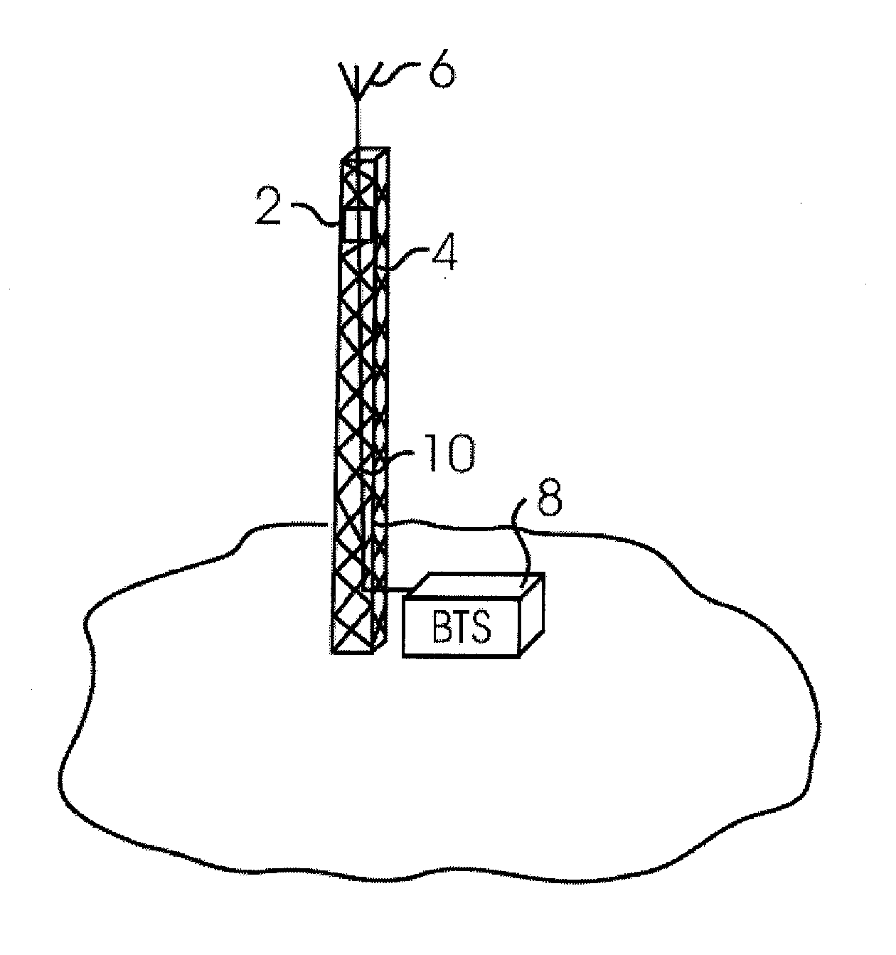
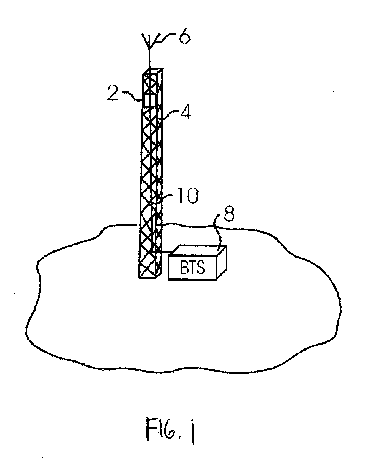
[0028]FIG. 1 illustrates a typical layout for an RF device 2 (e.g., TMA, MHA, and TMB). The RF device 2 may include filter and / or amplification functionality. The RF device 2 is disposed on a tower 4 or other elevated structure adjacent to an antenna 6. The RF device 2 is coupled to the antenna 6 and a base station (BTS) 8 via coaxial cable 10. The RF device 2 may be powered by a separate power line (not shown) or, alternatively, the low noise amplifier (LNA) and any other electronics may be powered through current provided in the coaxial cable 10. In one aspect, the RF device 2 is located on the tower 4 within ten feet of the antenna 6. In still other embodiments, the RF device 2 is located within six or even less than three feet of the antenna 6. The closer the RF device 2 is positioned adjacent to the antenna 6, the smaller the insertion loss created by the cabling connecting the RF device 2 to the antenna 6. In another alternative aspect of the invention, the RF device 2 is inte...


PUM


Abstract

A RF device such as a tower mounted amplifier (TMA), mast-head amplifier (MHA), or Tower Mounted Boosters (TMB) includes a housing having a plurality of cavities and an input and an output, the input being coupled to the antenna and the output being coupled to a base station. The housing includes a transmission path holding multiple coaxial resonators. The housing further includes multiple receive paths including at least one path having a plurality of cavities, each cavity containing a dielectric resonator. The metallic transmit resonator nearest the antenna input is coupled to the first dielectric resonator via a common resonant wire. The last dielectric resonator in the receive path is coupled to a first metallic resonator of a downstream clean-up filter via another common resonant wire.

Description

RELATED APPLICATIONS [0001] This application is a continuation-in-part of U.S. application Ser. No. 11 / 257,891 filed on Oct. 25, 2005, which itself claims priority to U.S. Provisional Application No. 60 / 623,552 filed on Oct. 29, 2004. This application also claims priority to U.S. Provisional Patent Application No. 60 / 746,366 filed on May 4, 2006. The above-noted applications are incorporated by reference as if set forth fully herein.FIELD OF THE INVENTION [0002] The field of the invention generally relates to low noise figure radiofrequency (RF) devices such as tower mounted amplifiers (TMA's) used in wireless applications. More specifically, the field of the invention relates to the specific design features that are used to produce both a low noise figure and rejection in compact devices. These designs have applications in Tower Mounted Amplifiers (“TMAs”) or Mast-Head Amplifiers (“MHAs”), Tower Mounted Boosters (“TMBs”) or any other application where low noise figure, rejection of...

Claims


Application Information

Patent Timeline
IPC IPC(8): H04B7/185H04M1/00
CPCH01P1/2053H01P1/2084H04B1/18H01Q1/246H01Q23/00H01P7/10
Inventor EDDY, MICHAEL M.HEY-SHIPTON, GREGORY L.
Owner ANTONE WIRELESS CORP
Why Eureka
Try Eureka