
Optical techniques and system for 3-D characterization of ultrasound beams

Active Publication Date: 2007-09-06
UNITED STATES GOVERNMENT AS REPRESENTED BY THE SEC DEPT OF HEALTH & HUMAN SERVICES +2
View PDF4 Cites 18 Cited by
  • Summary
  • Abstract
  • Description
  • Claims
  • Application Information

AI Technical Summary

Benefits of technology

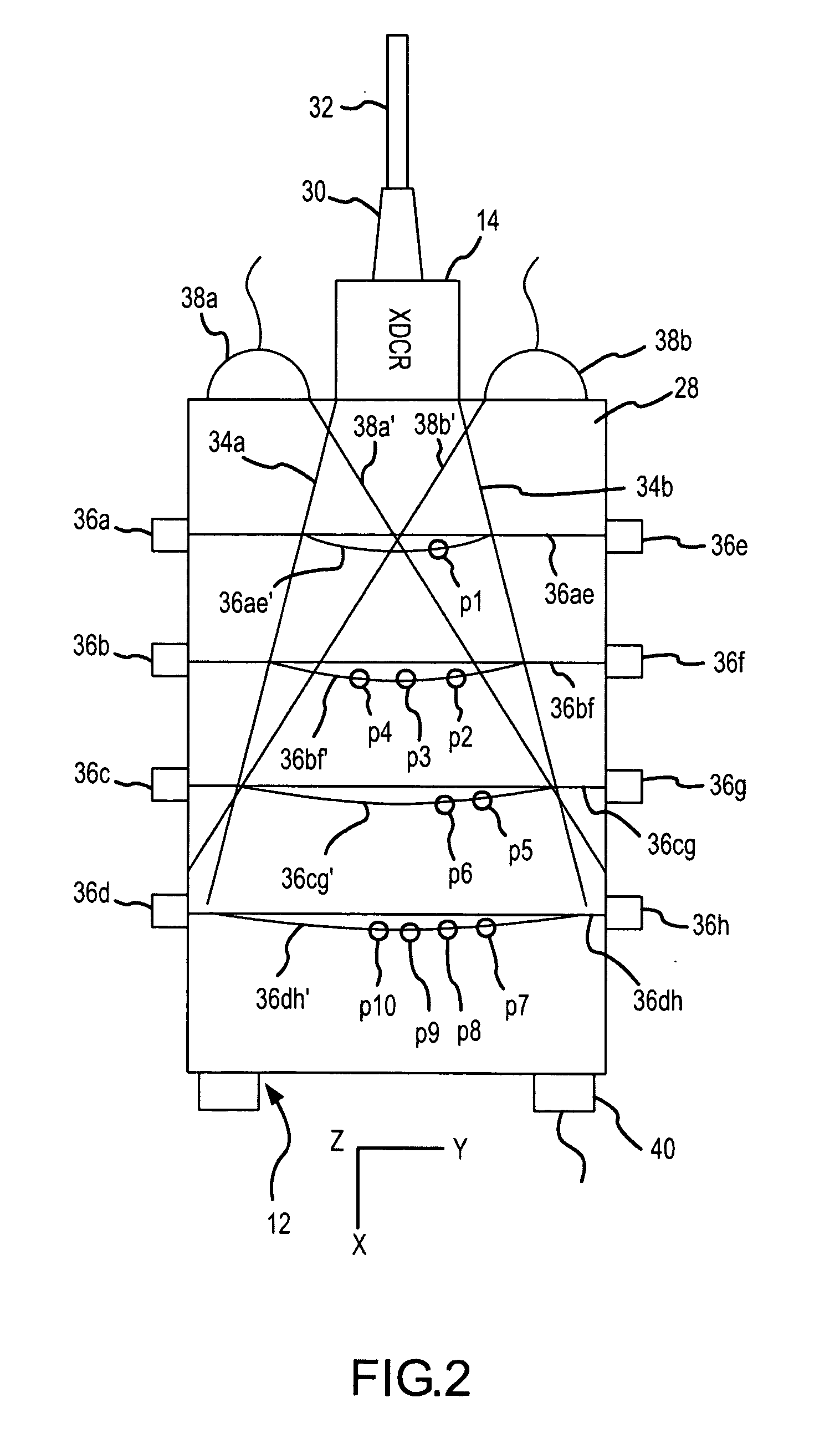
[0012] The at least one optical transmitter may illuminate at least some seed particles in a slicewise two-dimensional, or linewise one-dimensional, manner, and may further pulse illuminate the seed particles. The at least one optical transmitter may be a solid state laser device, optionally including beam shaping optics. The at least one optical receptor may be positioned orthogonally to a direction in which the streamable immersant may flow, and may be a digital camera or an optical temperature measurement device, such as an infrared or ultraviolet thermographic temperature measurement device. Both the optical transmitter and the optical receptor may be incorporated in a single optical device. Any thermographic temperature signal returning from illuminated seed particles is preferably selected to pass through the immersant such that it can be optically detected by the at least one optical receptor outside the immersant volume. For example, fluorescent seed particles emit wavelengths, such as ultraviolet wavelengths, that can pass through many types of materials with minimal loss.

Problems solved by technology

High power acoustic fields, such as are employed in the practice of medical High Intensity Focused Ultrasound (HIFU) therapy or surgery, are very difficult to measure, as their extreme intensities damage measurement instrumentation.
Furthermore, propagation nonlinearities are frequently present, if not dominating.
This testing methodology is far from optimal, however, as some of the effect of HIFU is attributable to naturally occurring non-linear high-power phenomena.
Consequently, the field of HIFU devices finds itself in the position of lacking metrics related to non-linear operational phenomena.

Method used


Image

  • Optical techniques and system for 3-D characterization of ultrasound beams
  • Optical techniques and system for 3-D characterization of ultrasound beams
  • Optical techniques and system for 3-D characterization of ultrasound beams

Examples


Embodiment Construction

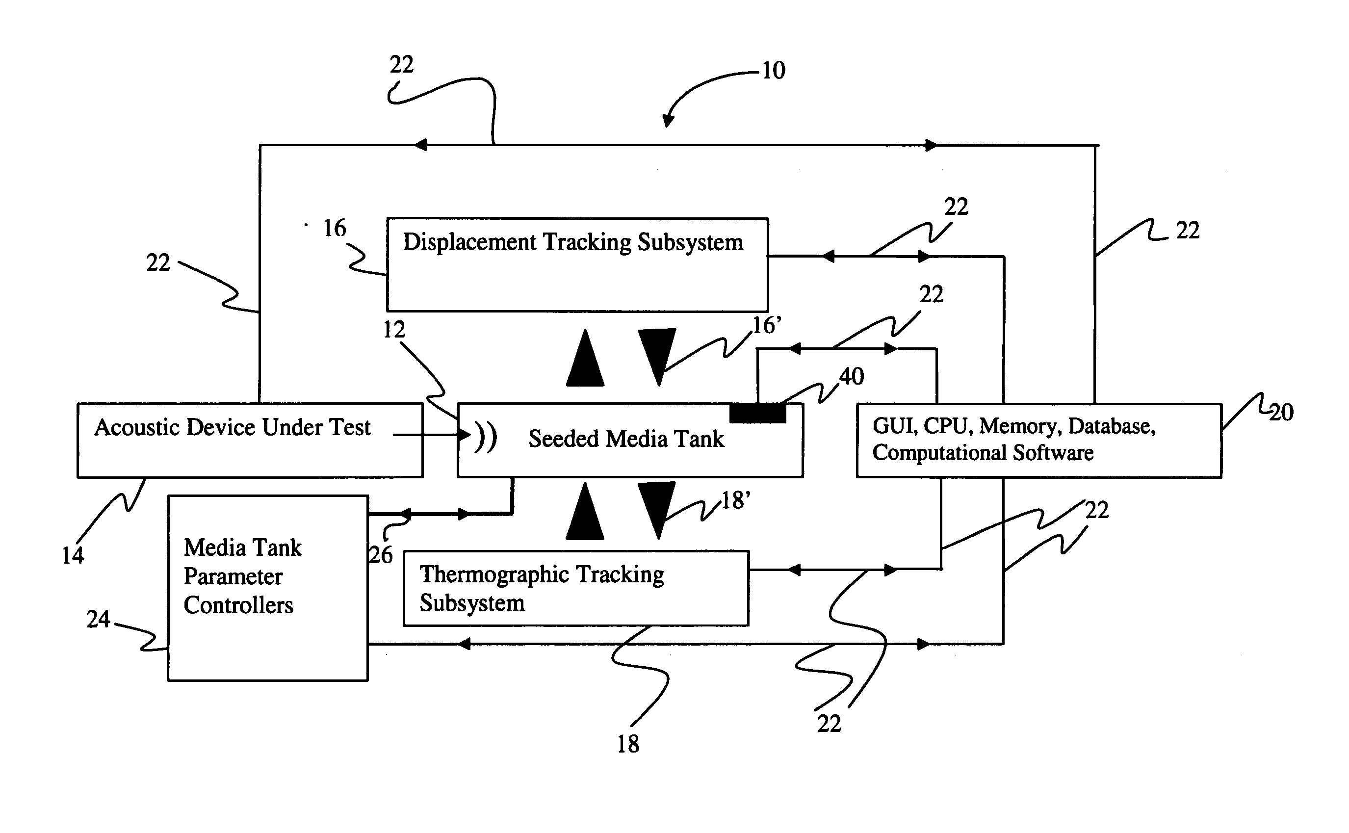
[0023] The present invention applies optical flow and temperature measurement techniques to characterize high power acoustic beams. The invention also applies numerical modeling techniques to back-calculate the acoustic pressure or intensity fields based on the flow and / or temperatures that are optically measured in a sonicated and seeded test medium. The invention may advantageously be used to directly characterize full power acoustic beams, including modeling the behavior thereof in tissue, thereby avoiding the need to infer high power, non-linear behavior from low power, linear test results. For example, the present invention provides a method of determining an unknown high power ultrasonic beam intensity map from acoustic streaming measurements, acoustic heating measurements, or both acoustic streaming and acoustic heating measurements.

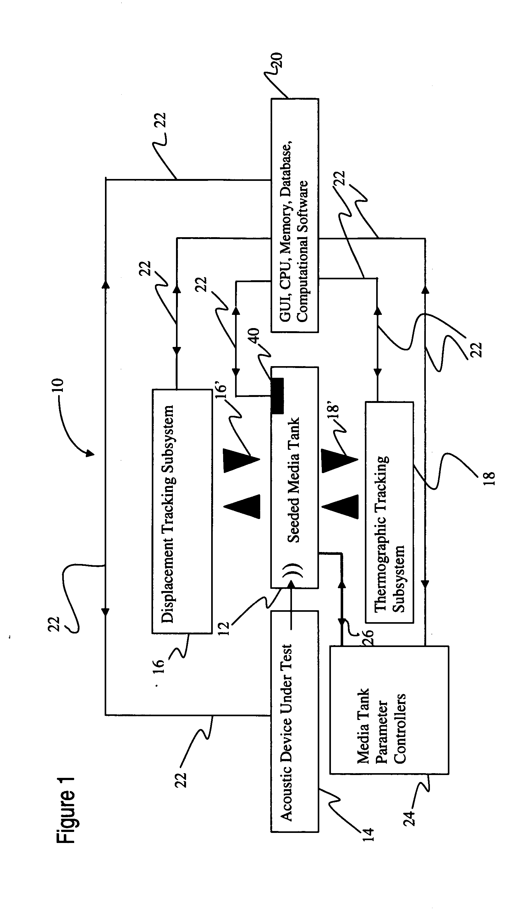
[0024]FIG. 1 is a block diagram of an optical system 10 for characterization of acoustic beams according to an embodiment of the present inventi...


PUM


Abstract

A system for optically characterizing an acoustic beam generally includes an immersant, which is an immersion medium seeded with a plurality of seed particles that respond to illumination with fluorescence indicative of at least one parameter of the immersant such as flow or temperature. Optical transmitters illuminate the immersant slicewise, and optical receptors receive the fluorescence in order to generate a three-dimensional map of the parameter over time. A processor back-calculates one or more characteristics of an acoustic beam that results in the map. The processor initially generates a behavior model of an acoustic beam propagating in the immersant by utilizing initial guesses for the characteristics. The initial guess model is compared to the map, and an optimization routine is used to refine the initial guesses. The process repeats iteratively with refined guesses until the difference between the model and the map is minimized.

Description

CROSS-REFERENCE TO RELATED APPLICATIONS [0001] This application claims the benefit of U.S. provisional application No. 60 / 752,630, filed 21 Dec. 2005, which is hereby incorporated by reference as though fully set forth herein.BACKGROUND OF THE INVENTION [0002] a. Field of the Invention [0003] The present invention is directed to optical techniques for non-invasively performing three-dimensional characterization of ultrasound beams. In particular, the present invention is directed to optical techniques for characterizing high power acoustic beams and fields, including with respect to their non-linearities. [0004] b. Background Art [0005] High power acoustic fields, such as are employed in the practice of medical High Intensity Focused Ultrasound (HIFU) therapy or surgery, are very difficult to measure, as their extreme intensities damage measurement instrumentation. Furthermore, propagation nonlinearities are frequently present, if not dominating. [0006] Thus, existing HIFU transduce...

Claims


Application Information

Patent Timeline
IPC IPC(8): G01H9/00
CPCG01H9/00
Inventor SLIWA, JOHN W. JR.HARIHARAN, PRASANNAROBINSON, RONALD A.MYERS, MATTHEW R.MARUVADA, SUBHABANERJEE, RUPAK K.HARRIS, GERALD R.
Owner UNITED STATES GOVERNMENT AS REPRESENTED BY THE SEC DEPT OF HEALTH & HUMAN SERVICES
Learn More