Light emitting diode projection system
a technology of light-emitting diodes and projection systems, which is applied in the direction of lighting and heating apparatus, waveguides, instruments, etc., can solve the problems of increasing the luminous emittance of led projection sources, and achieves improved performance, improved coupling efficiency of available output, and increased luminous emittance
- Summary
- Abstract
- Description
- Claims
- Application Information
AI Technical Summary
Benefits of technology
Problems solved by technology
Method used
Image
Examples
embodiment 130
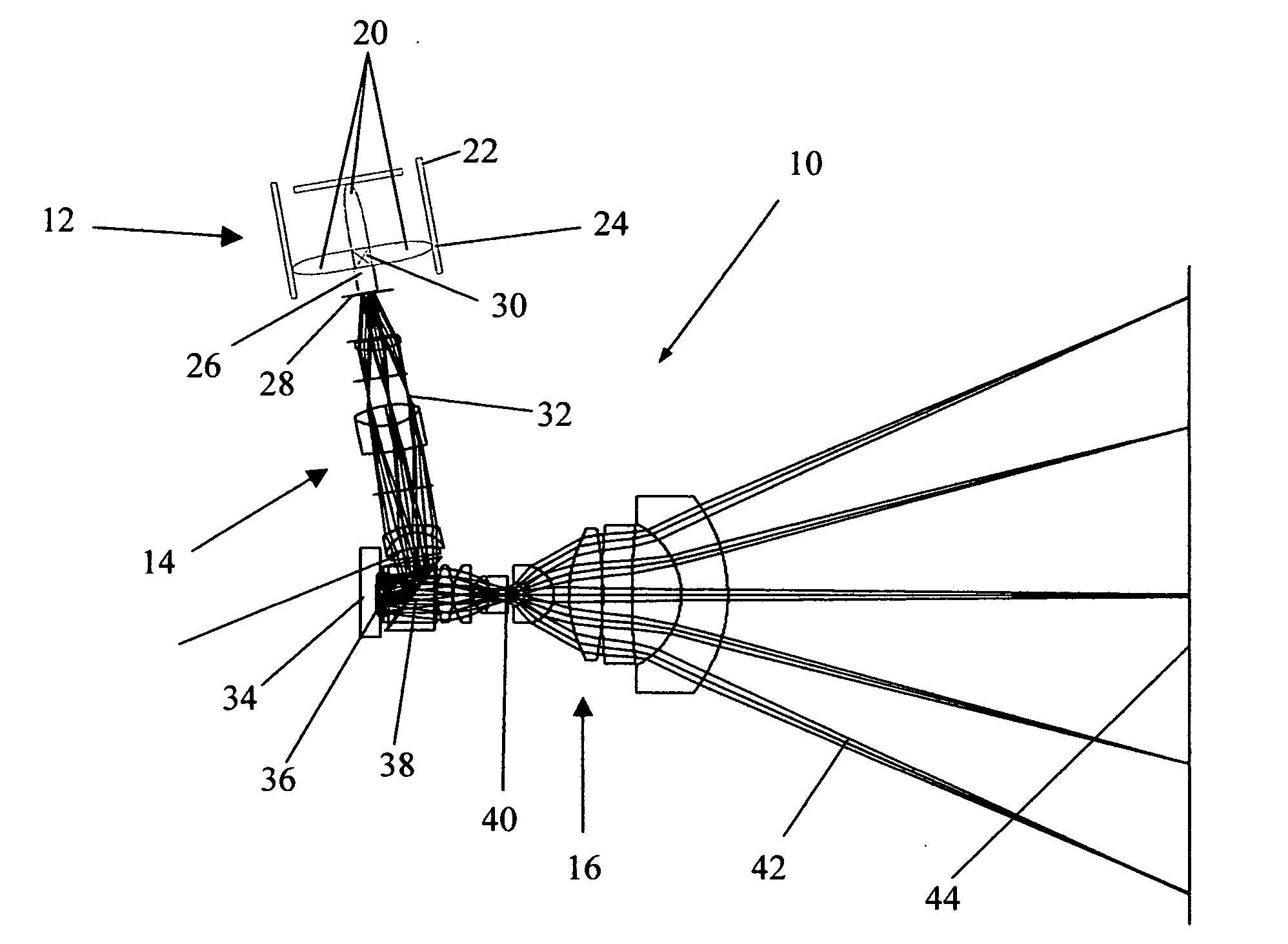
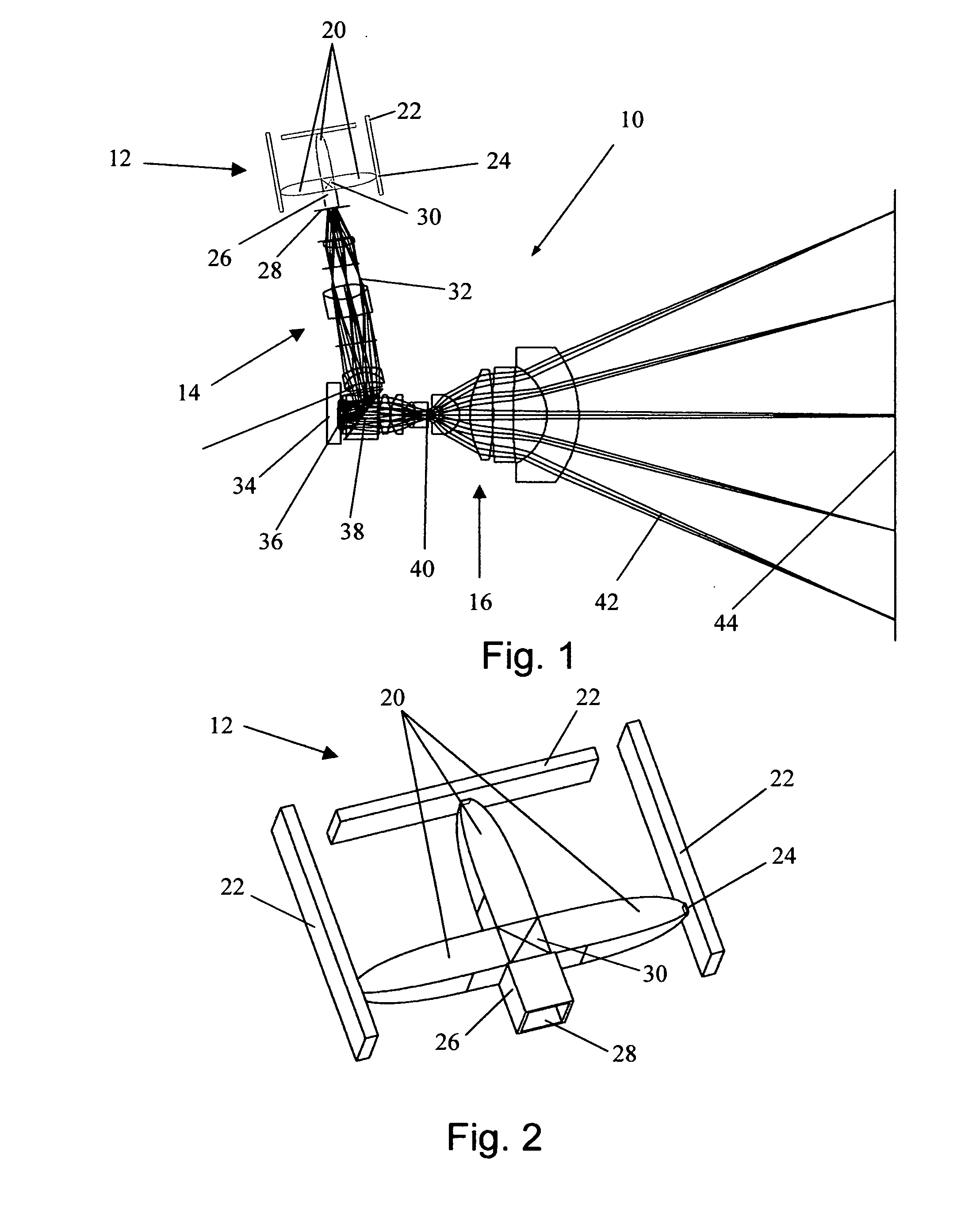
[0075]FIG. 14 shows an alternative coupling embodiment 130 of the LED projection source of FIG. 2 wherein common elements retain their original identification. Here, LED die or die arrays are attached to high thermally conductive boards 132 (typical) and coupled into input apertures 24 of CPCs 20, which can be either solid or hollow, with or without a conical input section. The output of the leftmost CPC 20 enters into a light guiding prism 138. The light is reflected through 90 degrees by the hypotenuse of 138, which is coated with a high reflectivity coating. As was the case for the prism 30 of FIG. 2, the prisms and rectangular glass sections 138, 140, 142, 143, 144, 146, 148, 134, and 136 use TIR to light pipe the light within their input dimensions so as to maintain the compact size with its inherent packaging and cost advantages. The total optical path between the exit aperture 46 of each of the three colors of LED source CPCs 20 and the output aperture 28 are substantially th...
embodiment 160
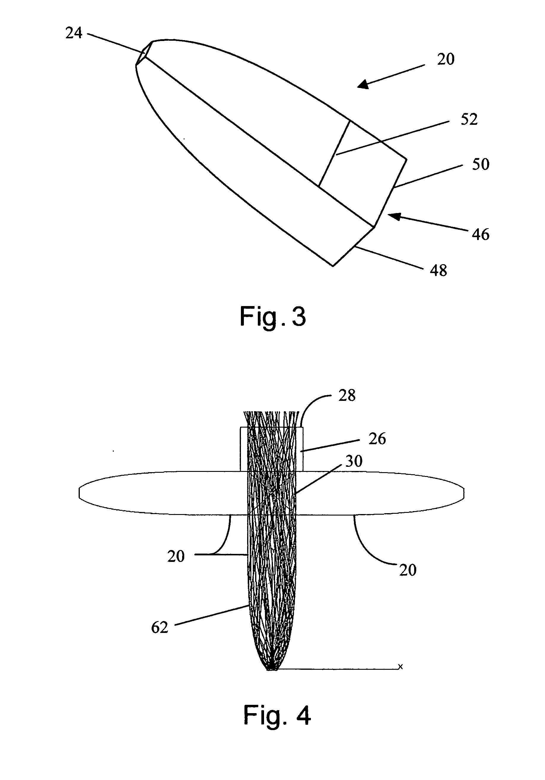
[0077]Reference is now made to FIGS. 16A and 16B which show an alternative embodiment 160 of a rectangular CPC for which the shape of the collection optic between the horizontal and vertical axes of the CPC of FIG. 3 are substantially the form of a CPC that vary continuously lengthwise (i.e. in meridonal planes passing through the surface and optical axis) from the vertical to horizontal. The points represented by 166, 168, 170, and 172 are all end points of differently shaped profiles but each of CPC form. Thus, at angles in a direction along the diagonals, passing through CPC end point 166, for example, and angles in between the horizontal and vertical CPC end points 170 and 172, represented by CPC end point 166, the form is still that of a CPC. This results in an optic that deviates from the simple rectangular cross section of the CPC of FIG. 3, that yields a substantially circular rather than rectangular far field. Thus, the compound CPCs of FIGS. 16A and 16B result in a rectang...
PUM
 Abstract
Description
Claims
Application Information
 - R&D
- Intellectual Property
- Life Sciences
- Materials
- Tech Scout
- Unparalleled Data Quality
- Higher Quality Content
- 60% Fewer Hallucinations
Browse by: Latest US Patents, China's latest patents, Technical Efficacy Thesaurus, Application Domain, Technology Topic, Popular Technical Reports.
© 2025 PatSnap. All rights reserved.Legal|Privacy policy|Modern Slavery Act Transparency Statement|Sitemap|About US| Contact US: help@patsnap.com


