Technique for efficiently and dynamically maintaining bidirectional forwarding detection on a bundle of links

a technology of bidirectional forwarding and bundles, applied in the field of computer networks, can solve the problems of devices destroying or closing the bgp session, nodes may not be able to communicate with one of their neighboring nodes, etc., and achieves the effects of reducing the number of nodes

Active Publication Date: 2007-09-06
CISCO TECH INC
View PDF12 Cites 109 Cited by
  • Summary
  • Abstract
  • Description
  • Claims
  • Application Information

AI Technical Summary

Benefits of technology

[0018] Advantageously, the novel technique efficiently and dynamically maintains BFD on a bundle of links in a computer network. By alternating between one or more standby BFD sessions on corresponding LCs as the active BFD session for a bundle of links, the novel technique provides greater performance, scalability, and reliability over a centralized BFD session. For instance, the BFD sessions on LCs may continue to operate regardless of a failure of a centralized process (e.g., a route processor, RP) managing the LCs. Also, by maintaining standby BFD sessions, more rapid handling of link and / or LC failure is possible, thus more aggressive BFD timeouts may be used. Further, the dynamic nature of the novel technique (e.g., selecting the active BFD session) alleviates the need for cumbersome manual configuration.

Problems solved by technology

For example, the node may become unable to communicate with one of its neighboring nodes, e.g., due to a link failure between the nodes or the neighboring node failing, such as going “off line,” etc.
Notably, in the event the Hold Time has expired, the devices may “break” (i.e., tear down or close) the BGP session.
In many situations, however, the large number of BFD messages sent between the nodes may violate various BFD parameters, such as, e.g., maximum packet transmissions or time between packets as agreed upon during BFD session initialization (negotiation).
Furthermore, the two routers may be connected to the switch by a different number of links (e.g., a link bundle from each router terminates at the switch), so a one-to-one mapping of BFD messages on individual links is not possible.
A major disadvantage to operating a centralized BFD session for link bundles is that if the RP (control card) fails, the centralized BFD session also fails, resulting in a false indication of link bundle failure where at least one LC hosting the link bundle is still operational.
Clearly, for many applications, the centralized BFD session approach is unreliable.
Further disadvantages include poor scalability for multiple link bundles, and decreased performance.

Method used


Image

  • Technique for efficiently and dynamically maintaining bidirectional forwarding detection on a bundle of links
  • Technique for efficiently and dynamically maintaining bidirectional forwarding detection on a bundle of links
  • Technique for efficiently and dynamically maintaining bidirectional forwarding detection on a bundle of links

Examples


Embodiment Construction

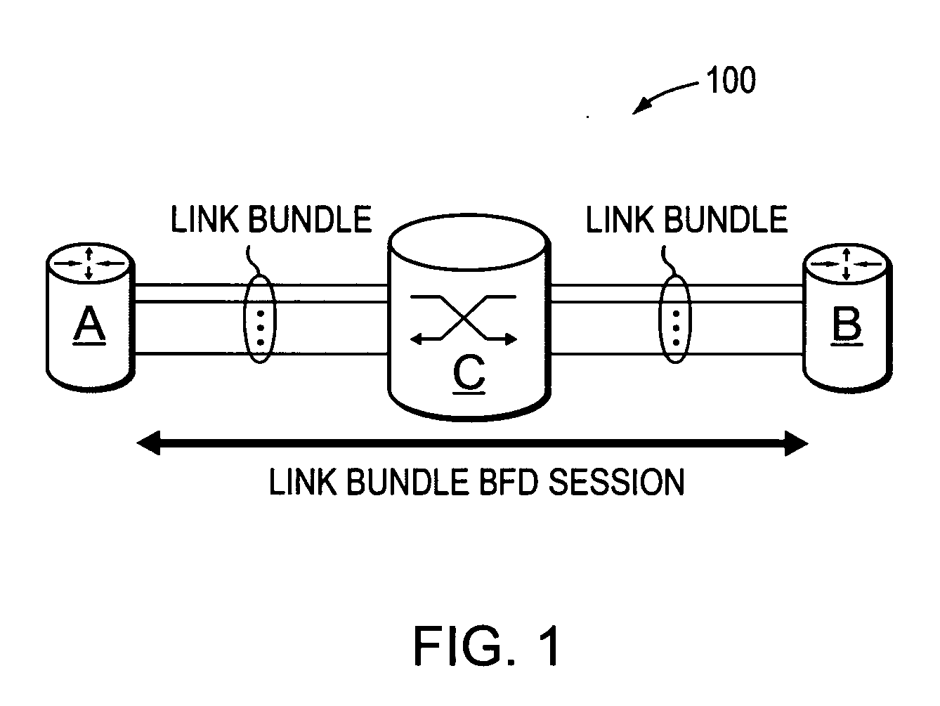
[0028]FIG. 1 is a schematic block diagram of an exemplary computer network 100 comprising a plurality of nodes A-C, such as routers, switches, or other network devices, interconnected as shown. For instance, node A may be connected to node C via a plurality of links arranged as a first bundle interface (link bundle), and node B may be connected to node C via a plurality of links arranged as a second link bundle. Illustratively, nodes A and B may be embodied as routers (layer 3), while node C may be embodied as a switch (layer 2). As such, the link bundles may appear to each of the routers A and B as a single link bundle (layer 3) from A to B, as will be understood by those skilled in the art. The nodes may be a part of one or more autonomous systems, routing domains, or other networks or subnetworks. These examples are merely representative. Those skilled in the art will understand that any number of routers, switches, nodes, links, etc. may be used in the computer network 100 and c...


PUM


Abstract

A technique efficiently and dynamically maintains bidirectional forwarding detection (BFD) on a bundle of links in a computer network. According to the novel technique, one or more “standby” BFD sessions may be established on one or more corresponding line cards (LCs), the LCs having one or more links of the bundle (bundle links). Once established, one of the standby BFD sessions may be selected as an “active” BFD session based on activity of one of the bundle links of the corresponding LC. Also, BFD messages may be transmitted from one of the bundle links of the active BFD session, e.g., the link receiving BFD messages. In response to inactivity of the transmitting link (e.g., failure, removal, etc.), the active BFD session may switch to another available active bundle link, and if no other active bundle links are available to the active BFD session, one of the standby BFD sessions is selected as the new active BFD session. In the event no other standby BFD sessions exist, the link bundle is determined to have failed.

Description

BACKGROUND OF THE INVENTION [0001] 1. Field of the Invention [0002] The present invention relates to computer networks and more particularly to maintaining bidirectional forwarding detection (BFD) on a bundle of links in a computer network. [0003] 2. Background Information [0004] A computer network is a geographically distributed collection of interconnected subnetworks, such as local area networks (LAN) that transport data between network nodes. As used herein, a network node is any device adapted to send and / or receive data in the computer network. Thus, in this context, “node” and “device” may be used inter-changeably. The network topology is defined by an arrangement of network nodes that communicate with one another, typically through one or more intermediate nodes, such as routers and switches. In addition to intra-network communications, data also may be exchanged between neighboring (i.e., adjacent) networks. To that end, “edge devices” located at the logical outer-bound of ...

Claims


Application Information

Patent Timeline
Patent Type & Authority Applications(United States)
IPC IPC(8): H01L21/76H04L45/24H04L45/18H04L45/243H04L45/28H04L45/58H04L45/60
CPCH04L45/00H04L45/22H04L45/24H04L45/245H04L43/10H04L45/58H04L45/60Y02B60/33H04L45/28Y02D30/50H04L45/247H04Q2213/13162H04Q2011/0081H04L41/0663
Inventor RAHMAN, RESHAD A.TOSCANO, DAVID P.MASSE, SYLVAINWARD, DAVID D.KETLEY, NEIL R.
Owner CISCO TECH INC
Why Eureka
Try Eureka