

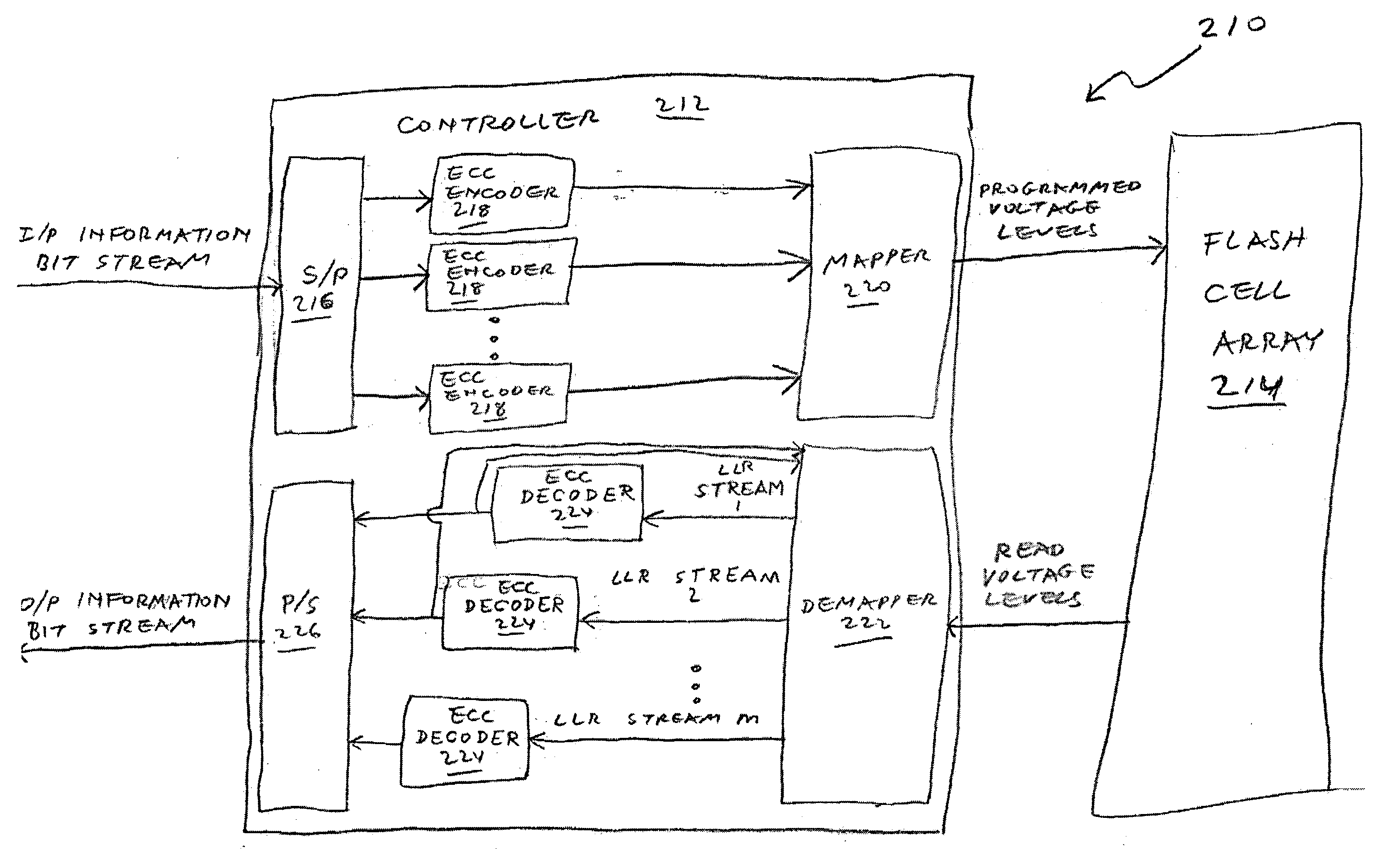
Multi-bit-per-cell flash memory device with non-bijective mapping
a multi-bit per-cell, flash memory technology, applied in the field of multi-bit per-cell flash memory, can solve the problems of increasing the number of voltage levels, affecting the reliability of flash memory, and affecting the performance of flash memory, so as to achieve the effect of improving flash reliability and low flash cos
- Summary
- Abstract
- Description
- Claims
- Application Information
AI Technical Summary
Benefits of technology
Problems solved by technology
Method used
Image

Examples
example 1
Computing the Capacity of Flash Memory 10 of FIG. 4
[0137]The programming and read voltage levels are: X=Y=[0 0.333 0.666 1] [Volts],
[0138]The flash memory suffers from an additive Gaussian noise with standard deviation σ=150 [mV],
[0139]Each programming level is programmed with equal probability:
P(Xi)=0.25 for i=1,2,3,4
[0140]The transition probabilities are computed as follows:
P(YjXi)=Q(Yj-Xi-0.1667σ)-Q(Yj-Xi+0.1667σ)forj=2,3P(YjXi)=Q(Yj-Xi-0.1667σ)forj=1,4where,Q(x)=∫x∞12π-x2 / 2
[0141]Then the flash capacity is given by:
C=∑i=14∑j=14P(Xi)P(YjXi)log2(P(YjXi)∑k=14P(Xk)P(YjXk))=1.1612IBPC
example 2
Computing the capacity of Flash Memory 110 of FIG. 5, Embodiment of Tables 4 and 5
[0142]The programming and read voltage levels are: X=Y=[0 0.5 1] [Volts],
[0143]The flash memory suffers from an additive Gaussian noise with standard deviation σ=150 [mV],
[0144]The non-bijective mapping induces the following non-uniform distribution over the programming voltage levels:
P(X)=[0.375 0.25 0.375]
[0145]The transition probabilities are computed as follows:
P(YjXi)=Q(Yj-Xi-0.25σ)-Q(Yj-Xi+0.25σ)forj=2P(YjXi)=Q(Yj-Xi-0.25σ)forj=1,3
[0146]Then the flash capacity is given by:
C=∑i=13∑j=13P(Xi)P(YjXi)log2(P(YjXi)∑k=13P(Xk)P(YjXk))=1.2224IBPC
Annex B: Formal Function-Related Definitions
[0147]Definition (one-to-one): A function f is said to be one-to-one (injective) if and only if f(x)=f(y) implies x=y. Otherwise, the function is many-to-one: there exists at least one argument pair (x,y) such that x≠y and f(x)=f(y).
[0148]Definition (onto): A function f from a set A to a set B is said to be onto (surjecti...
PUM
 Abstract
Description
Claims
Application Information