Storage system and control method for the same

Inactive Publication Date: 2007-09-06
HITACHI LTD
View PDF9 Cites 38 Cited by
  • Summary
  • Abstract
  • Description
  • Claims
  • Application Information

AI Technical Summary

Benefits of technology

[0010] For example, if the plurality of logical devices allocated to the logical volume from which data-read has been requested is in a power-off state, the storage system selects the logical device having the oldest power-off time from among the plurality of logical devices allocated to the logical volume from which data-read has been requested; turns on the power supply for the selected logical device; and reads data from the selected logical device. Accordingly, it is possible to reduce the incidence of a particular disk drive being in a power-off state for a long period of time, and even if a failure occurs during the power-off period, that failure can be detected at an earlier stage.
[0011] For example, if some of the plurality of logical devices allocated to the logical volume from which data-read has been requested is in a power-on state, the storage system reads data from any of the powered-on logical devices. Accordingly, it is possible to reduce the frequency of a disk drive being switched on/off, and also reduce the proportion of disk drives that have been powered on in a plurality of disk drives.
[0012] For

Problems solved by technology

However, if a disk drive is frequently switched on/off, or if the rotation of a disk drive is frequently started/stopped, that accelerates the disk drive's degradation with time, resulting in an increase in both the failure probability and power consumption.
For example, where the same data is distributed and stored in a plurality of disk drives so that the data can be read from any disk drive, if the data is read evenly from every disk drive, the frequency of each disk drive being switched on/off will increase, causing a problem involving an increase in the disk drive failure probability and powe

Method used


Image

  • Storage system and control method for the same
  • Storage system and control method for the same
  • Storage system and control method for the same

Examples


embodiment 1

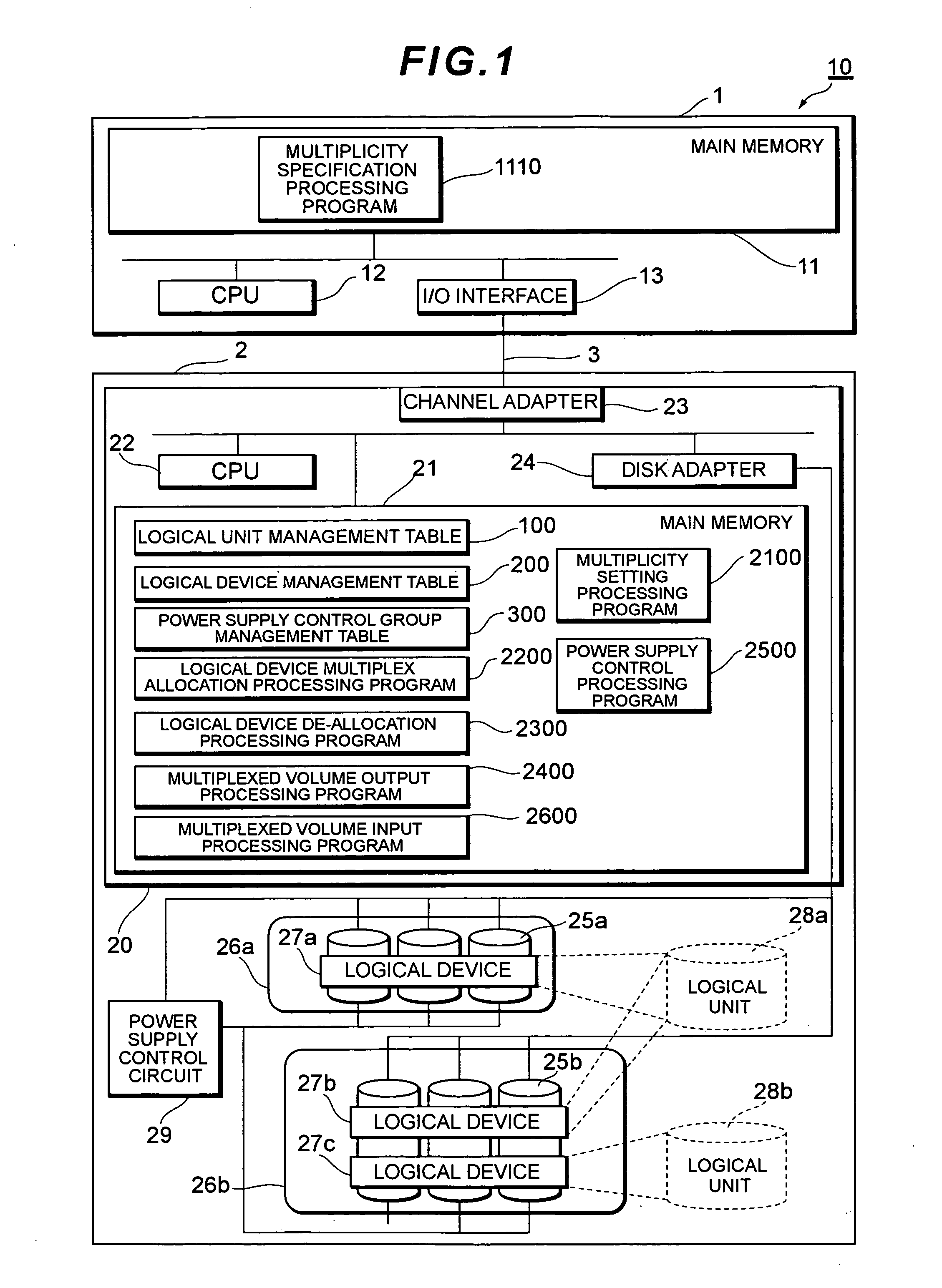
[0031]FIG. 1 shows the hardware configuration of a computer system 10 according to Embodiment 1. The computer system 10 includes a host computer 1 and a storage system 2. The host computer 1 and the storage system 2 are connected via a communication network 3. The communication network 3 is, for example, a SAN (Storage Area Network), LAN (Local Area Network), WAN (Wide Area Network), internet, dedicated line, public line, or similar.

[0032] The host computer 1 includes a main memory 11, a CPU 12 and an I / O interface 13. The CPU 12 loads, interprets and executes the instruction code in a multiplicity instruction processing program 1100 stored in the main memory 11. The I / O interface 13 is an interface for accessing the storage system 2 via the communication network 3, and it is, for example, a host bus adapter or similar.

[0033] The multiplicity instruction processing program 1100 instructs the storage system 2 about the multiplicity for a logical volume, which is a logical storage a...

embodiment 2

[0132]FIG. 14 shows the hardware configuration of a computer system 10a according to Embodiment 2. The computer system 10a includes a host computer 1, a storage system 2a and a storage system 2s. The host computer 1 is connected with the storage system 2a via a communication network 3a. The storage system 2a is connected with the storage system 2s via a communication network 3s.

[0133] The storage system 2a includes a controller 20a, a plurality of disk drives 25a, and a power supply control circuit 29a. The controller 20a includes main memory 21a storing various tables, programs, etc., a CPU 22a executing various control processing, a channel adapter 23a functioning as a host interface for connection with the host computer 1, a channel adapter 23b functioning as an initiator port for connection with the storage system 2s that exists externally, and a disk adapter 24a functioning as a drive interface to control data input / output to / from the disk drives 25a.

[0134] The main memory 21...


PUM


Abstract

When a storage system receives a request from a host computer to read data from a logical unit, the storage system selects a logical device from which data is to be read, in accordance with the power supply status and power-off time for each logical device allocated to the logical unit, turns on the power supply for the selected logical device, and reads data from that device. When the storage system receives a request from a host computer to write data to a logical unit, it turns on the power supply for each logical device allocated to the logical unit and performs multiplex-writing of data for each logical device.

Description

CROSS-REFERENCES TO RELATED APPLICATIONS [0001] This application relates to and claims priority from Japanese Patent Application No. 2006-58567, filed on Mar. 3, 2006, the entire disclosure of which is incorporated herein by reference. BACKGROUND OF THE INVENTION [0002] The present invention relates to a storage system that provides a host computer with a logical volume multiplexed with a plurality of logical devices, and a control method for the same. [0003] In recent years, data life cycle management (DLCM) has been attracting attention as a method for managing a storage system. DLCM is a concept realizing a more cost efficient data management method by managing data migration between storage systems according to the value of data changing with time. For instance, since an email system is positioned as a mission-critical enterprise system, it is necessary to use a high-end storage system having high performance and high reliability. Since access frequency will decrease for email t...

Claims


Application Information

Patent Timeline
IPC IPC(8): G06F12/00G06F1/32G06F12/16
CPCG06F1/3203G06F1/3268Y02B60/1246Y02B60/1217G06F11/004Y02D10/00
Inventor HOSOUCHI, MASAAKIHIRAIWA, YURIMAKI, NOBUHIRO
Owner HITACHI LTD
Why Eureka
Try Eureka