
Method for processing organic solvent-containing air

a technology of organic solvent and air, which is applied in the direction of organic chemistry, separation process, dispersed particle separation, etc., can solve the problems of oxidation catalyst exposed to a high temperature, oxidation catalyst performance decline, and enormous heat generation, and achieve the effect of increasing high thermal efficiency

Inactive Publication Date: 2007-09-13
NICHIAS CORP
View PDF9 Cites 5 Cited by
  • Summary
  • Abstract
  • Description
  • Claims
  • Application Information

AI Technical Summary

Benefits of technology

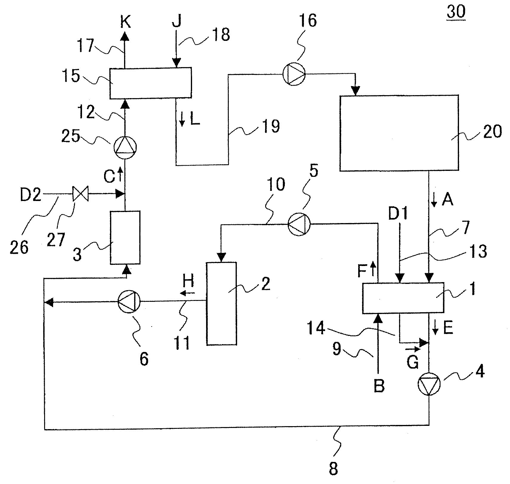
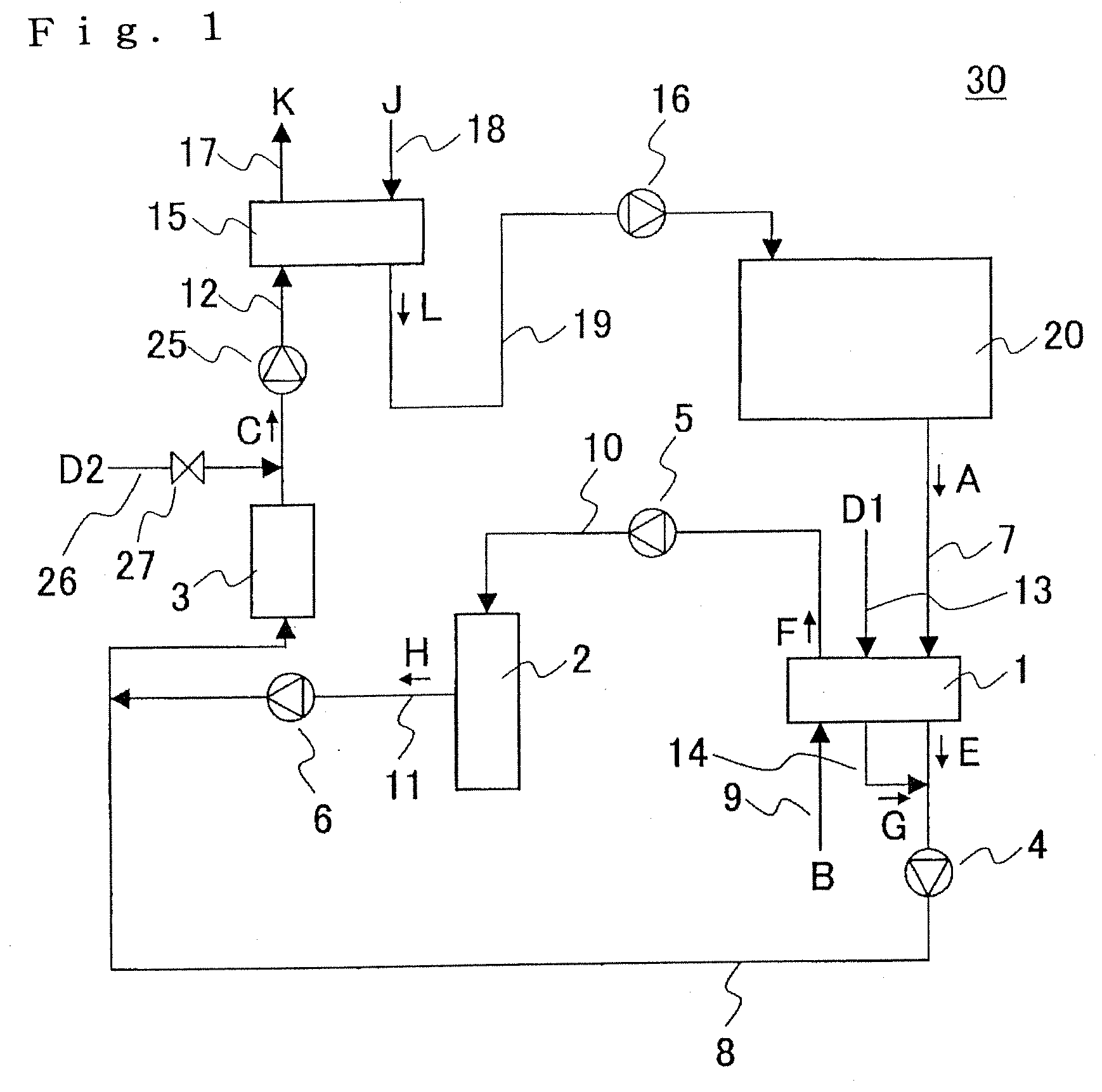
[0014]As a result of extensive research in order to achieve the above object, the present inventors have found that (1) if an absorption-treated air processed by an adsorber and a combustion furnace exhaust gas processed by a combustion furnace are mixed and the mixture is decomposed by oxidation using an oxidation-decomposition filter or the like, a stable operation can be ensured without increasing the content of the organic solvents in the purified air, even if the content of the organic solvents in the exhaust gas of the combustion furnace rapidly changes and that (2) because the purified air can be used as an air for regenerating a dehumidifying member, thermal efficiency can be improved. This finding has led to the completion of the present invention.
[0017]According to the method for processing an organic solvent-containing air of the present invention, a method capable of being operated in spite of a rapid fluctuation of the concentration of organic solvents in the air to be processed can be provided. Specifically, according to the method of the present invention, not only a rapid fluctuation of the concentration of organic solvents in the air to be processed does not accompany an increase in the organic solvent content in the air to be emitted into the atmosphere after processing, but also the combustion furnace exhaust gas can be used as an air for regenerating dehumidifying member, thereby ensuring increasing high thermal efficiency.

Problems solved by technology

Since such organic solvents are harmful, the organic solvents in the air discharged from these processes must be removed by an appropriate method.
Because the organic solvents burn by being catalyzed with an oxidation catalyst in the combustion furnace, an enormous heat is generated and the oxidation catalyst is exposed to a high temperature.
Since a platinum catalyst, of which the upper limit of the operating temperature is 500° C., is commonly used as the oxidation catalyst, if heated above 500° C., the oxidation catalyst decreases its performance due to deterioration by heat.
The organic solvents can be burnt only incompletely in the combustion furnace if the concentration of the organic solvents in the air supplied to the combustion furnace is too high.
That is, there is an upper limit to the concentration (content) of the organic solvents in the air which can be processed by the combustion furnace.
In regard to the fluctuation of the concentration which may cause trouble in the process, an increase of the concentration is so great that the concentration of the organic solvents must be reduced by introducing a great amount of external air.
However, since there is a limitation to the throughput of a combustion furnace, the amount of external air to be introduced is limited.
Thus, the problem could not be obviated in some cases by introducing an external air.
It is impossible for the combustion furnace alone to completely burn the organic solvent, in which case an unburned organic solvent may mix into the combustion furnace exhaust gas.
Moreover, since the combustion furnace exhaust gas may contain the unburned organic solvent even at a high temperature, it was impossible to use the combustion furnace exhaust gas for regenerating the dehumidifying member which has adsorbed moisture.
For this reason, the conventional method had a problem of extremely poor thermal efficiency.

Method used


Image

  • Method for processing organic solvent-containing air
  • Method for processing organic solvent-containing air
  • Method for processing organic solvent-containing air

Examples


example 1

[0050]An organic solvent-containing air was processed using the organic solvent-containing air processing system shown in FIG. 4 under the conditions shown in Table 1, provided that installation of the production plant 20 was omitted and an air of which the content of organic solvents was adjusted was directly introduced as the air A to be processed into the pipe 7 for supplying air to be processed. The results are shown in Table 2.

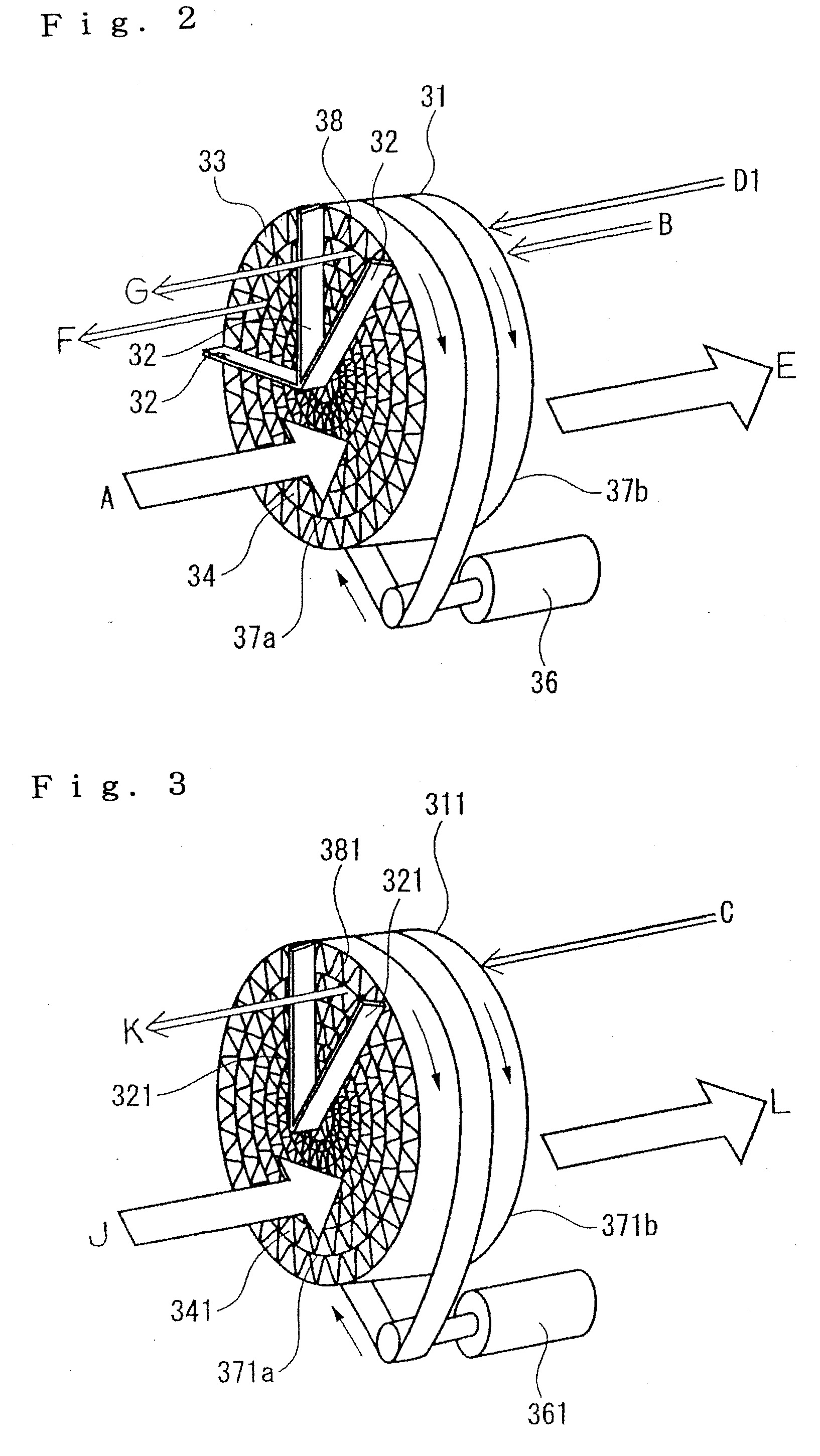
[0051]Adsorber 1[0052]Carrier: A rotor-shaped honeycomb structural carrier with a diameter of 400 mm and a length in the air-flow direction of 400 mm, made from silica-alumina fiber paper (thickness: 0.2 mm, void ratio: 90%) was prepared.[0053]Supported adsorbent: ZSM-5 zeolite (composition: Al0.64Si95.36O192)[0054]Ratio of adsorption zone, regeneration zone, and purge zone: 3:1:1

[0055]Combustion furnace 2[0056]Packed catalyst: Cordierite-supported platinum catalyst[0057]Packed bed: diameter: 0.5 m, length: 1 m

[0058]Oxidation-decomposition filter 3[0059]P...


PUM

PropertyMeasurementUnit
operating temperatureaaaaaaaaaa
temperatureaaaaaaaaaa

Abstract

A method for processing an organic solvent-containing air capable of being operated in spite of a rapid fluctuation of the concentration of organic solvents in the air to be processed and capable of using a combustion furnace exhaust gas as an air for regenerating dehumidifying member is provided. The method comprises carrying out simultaneously and continuously a dehumidification step (a), an adsorption-removing step (b), an adsorbing member-regeneration step (c), a combustion step (d), and a dehumidifying member-regeneration step (e) comprising mixing the adsorption-treated air produced in the adsorbing-removing step (b) with a combustion furnace exhaust gas produced in the combustion step (d) to obtain a mixed gas, decomposing the organic solvents in the mixed gas by oxidation, and causing the resulting purified gas to flow through the dehumidifying member which has adsorbed moisture, thereby regenerating the dehumidifying member.

Description

BACKGROUND OF THE INVENTION[0001]1. Field of the Invention[0002]The present invention relates to a method for continuously processing an organic solvent-containing air discharged from a production process, while supplying a dehumidified air to the production process. More particularly, the invention comprises simultaneously and continuously carrying out a dehumidification step of dehumidifying an air to be supplied to a production process by a dehumidifying member on which a dehumidification agent is supported, a dehumidifying member-regeneration step of regenerating the dehumidifying member which has adsorbed moisture, an adsorbing-removing step of removing organic solvents in the air to be processed by adsorbing the organic solvents in an adsorbing member containing an adsorbent such as zeolite supported thereon, an adsorbing member-regenerating step of regenerating the adsorbing member which has adsorbed the organic solvents, and a combustion step of burning the organic solvents ...

Claims


Application Information

Patent Timeline
Patent Type & Authority Applications(United States)
IPC IPC(8): B01D53/02
CPCB01D53/04B01D2257/704B01D53/8668B01D53/261Y02A50/20B01D53/00B01D53/02B01D53/26
Inventor KUROSAWA, MASAJIYAMASHITA, KATSUHIRODEGUCHI, TOMOHIRO
Owner NICHIAS CORP
Learn More