
Chalcopyrite Type Solar Cell

a solar cell and chalcopyrite technology, applied in the field can solve the problems of difficult selenide formation, high temperature cannot be used, and large energy efficiency of high temperature, and achieve the effect of increasing the open circuit voltage of chalcopyrite type solar cells

Inactive Publication Date: 2007-09-13
HONDA MOTOR CO LTD
View PDF5 Cites 90 Cited by
  • Summary
  • Abstract
  • Description
  • Claims
  • Application Information

AI Technical Summary

Benefits of technology

[0022] In Patent Document 3, various materials are listed as proposed materials for the substrate. However, all of the chalcopyrite type solar cells disclosed in Patent Document 3 are formed using glass substrates only. Therefore, it is not clear whether erosion can be avoided during selenide formation, even when other materials are used. For example, when a mica aggregate substrate, comprising mica particles bonded by a resin, is used as the substrate and provided within a stack, it is recognized that the stack tends easily to become disengaged from the mica aggregate substrate, and hence energy conversion efficiency is lowered.
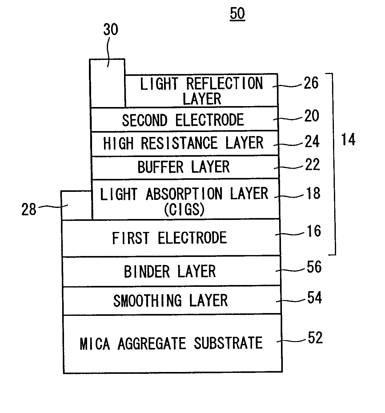
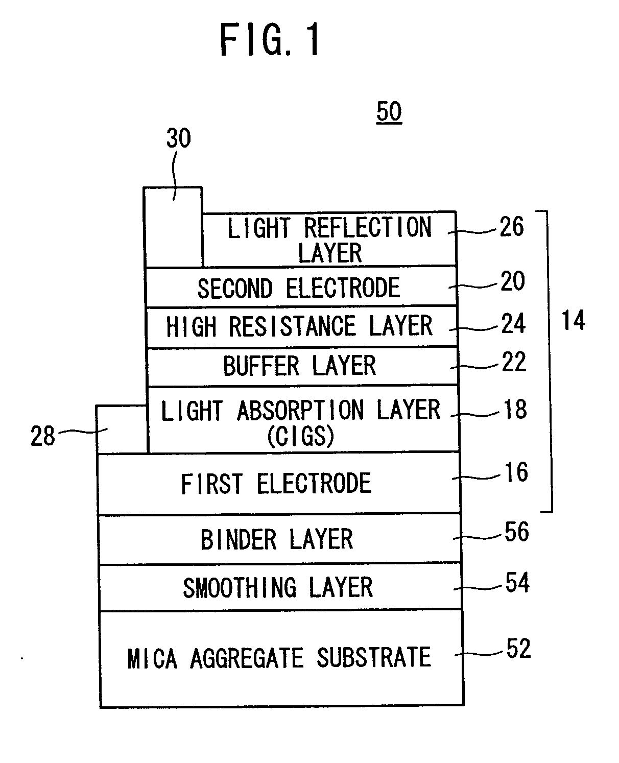
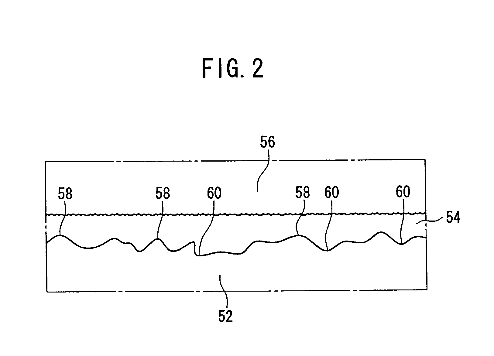
[0036] It is preferable for a smoothing layer containing one of SiN to SiO2 and having irregularities on an upper end surface thereof to be provided between the insulative substrate and the binder layer, wherein the irregularities of the smoothing layer are smaller than irregularities on an upper end surface of the insulative substrate. Accordingly, transfer of irregularities to the first electrode and the light absorption layer can be avoided. As a result, an advantage is obtained in that the open circuit voltage of the chalcopyrite type solar cell is increased.

Problems solved by technology

However, when a glass substrate is used, and the precursor is subjected to selenide formation, high temperatures cannot be used.
Therefore, it is difficult to advance selenide formation, so as to produce a composition in which the energy efficiency thereof is extremely large.
Further, other inconveniences arise because the substrate is thick.
Further, the produced chalcopyrite type solar cell has a large mass.
Additionally, since the glass substrate is essentially non-flexible, it is difficult to adapt the aforementioned process to a “roll-to-roll process” mass production method.

Method used


Image

  • Chalcopyrite Type Solar Cell
  • Chalcopyrite Type Solar Cell
  • Chalcopyrite Type Solar Cell

Examples


Embodiment Construction

[0042] A chalcopyrite type solar cell according to the present invention shall be explained in detail below with reference to the accompanying drawings, which exemplify preferred embodiments of the invention. Constitutive components, which are the same as those shown in FIG. 5, shall be designated using the same reference numerals, and detailed explanation thereof shall be omitted.

[0043]FIG. 1 is a schematic vertical sectional view illustrating a chalcopyrite type solar cell 50 according to an embodiment of the present invention. The chalcopyrite type solar cell 50 comprises a substrate 52, a stack 14, together with a smoothing layer 54 and a binder layer 56, which are interposed between the substrate 52 and the stack 14.

[0044] In this embodiment, the substrate 52 is formed of a mica aggregate. The term “mica aggregate” as used herein refers to a material obtained by sintering, after mixing powdery granular mica with a resin.

[0045] The mica aggregate is an insulator possessing an...


PUM


Abstract

A chalcopyrite type solar cell has a mica aggregate substrate formed by binding mica particulates with a resin. A multilayer body consisting of a first electrode, a light absorption layer and a second electrode is formed on the mica aggregate substrate with a smoothing layer and a binder layer interposed between the substrate and the body. The smoothing layer is preferably made of SiN or SiO2, and the binder layer is made of TiN or TaN.

Description

TECHNICAL FIELD [0001] The present invention relates to a chalcopyrite type solar cell having an insulative substrate containing mica. BACKGROUND ART [0002] A chalcopyrite type solar cell is a solar cell which includes, as a light absorption layer, a chalcopyrite compound represented by Cu(InGa)Se (hereinafter also referred to as “CIGS”). Special attention has been focused on this type of solar cell, since chalcopyrite type solar cells possess various advantages. For example, the energy conversion ratio of such solar cells is high, the optical deterioration due to aging is rarely caused, resistance to radiation is excellent, and the solar cell exhibits a wide light absorption wavelength range as well as a large light absorption coefficient. Thus, various investigations have been conducted in order to realize mass production of chalcopyrite type solar cells. [0003] As shown in FIG. 5, a chalcopyrite type solar cell 10 of this type is provided by disposing a stack 14 on a glass substr...

Claims


Application Information

Patent Timeline
IPC IPC(8): H01L31/00H01L31/04H01L31/0336H01L31/0392
CPCH01L31/0392Y02E10/541H01L31/0749H01L31/03923H01L31/03925Y02P70/50
Inventor YONEZAWA, SATOSHIHAYASHIDA, TADASHI
Owner HONDA MOTOR CO LTD
Learn More