Heat radiator and display unit

a technology of heat radiator and display unit, which is applied in the direction of lighting and heating apparatus, semiconductor devices for light sources, instruments, etc., can solve the problems of inability to meet the requirements of backlight unit, inability to provide satisfactory emission brightness, and relatively short life of cclf, so as to prevent color irregularities, enhance heat conductivity, and operate stably

Inactive Publication Date: 2007-09-13
SONY CORP
View PDF4 Cites 125 Cited by
  • Summary
  • Abstract
  • Description
  • Claims
  • Application Information

AI Technical Summary

Benefits of technology

[0021] The heat sink is disposed facing to a portion of the radiation plate through the back panel to constitute an overlap portion, where a plurality of mounting holes are formed in each of the radiation plate, back panel, and heat sink as to communicate with each other, and the radiation plate and heat sink are integrated with each other through the back panel by fixing members inserted in the mounting holes, thereby enhancing heat conductivity between the radiation plate and heat sink.
[0022] Heat generated by the lighting operation of the LEDs is conducted through the radiation plate to the back panel, and then conducted from the back panel to the heat sink, where the heat is radiated from the fins. The back panel having a small thickness is integrated with the radiation plate and heat sink by being sandwiched between them, thereby maintaining tight mounting between them, resulting in effective radiation of the heat generated in the LEDs. Therefore, in the hear radiator, uniform temperature distribution can be achieved over the entire surface of the transmissive display panel or other optical plates, thereby preventing occurrence of color irregularities and allowing respective components to stably operate.
[0023] By using the present invention, it is possible to reduce the thickness of the back panel, as well as to maintain tight mounting between the radiation plate, back plate, and heat sink that constitute a heat conduction path for radiating heat generated in the LEDs, to achieve effective heat radiation from the heat sink, to achieve stable light emission of LEDs, to prevent occurrence of color irregularities on the display panel, and to improve brightness and uniformity ratio. Further, by reducing the thickness of the back panel, it is possible to reduce the material cost and assembly man-hour.

Problems solved by technology

Such a backlight unit has some problems to be solved, with regard to the CCLF.
That is, the CCLF cannot provide satisfactory emission brightness; the life of the CCLF is comparatively short; brightness uniformity cannot be secured in the CCLF due to generation of low brightness area on the cathode side thereof; and the like.
Especially, in a large-sized television set of 30 inches or more, problems in terms of brightness level and brightness uniformity have become more prominent.
Further, there is a fear that heat generated from the LEDs is accumulated in the enclosed space formed on the back surface side of the liquid crystal panel to deform or transform optical plates.
There is also a fear that electronic components or integrated circuit elements are affected by heat to result in unstable operation.
However, the use of such a cooling fan allows dust included in the cooling air sucked from outside the unit to be adhere to the surfaces of the LEDs, thereby deteriorating the emission characteristics of the light emitted from the LEDs.
Since the heat conducting member blocks illumination light, such a heat radiator cannot directly be disposed within the enclosed space.
This makes it difficult to achieve adhesion between the base and back plate throughout the entire surfaces thereof to generate a gap therebetween, thereby deteriorating heat conduction efficiency.
It follows that heat conduction efficiency is reduced, failing to perform effective heat radiation.
Further, provision of the mounting portions to the radiation plate and heat sink on the back plate reduces the mechanical strength of the back plate and increases man-hours to screw up.
Further, intervention of the back plate between the heat radiation plate and heat sink impairs mechanical fixation between the heat radiation plate and heat sink as well as impairs heat conductivity therebetween.

Method used


Image

  • Heat radiator and display unit
  • Heat radiator and display unit
  • Heat radiator and display unit

Examples


Embodiment Construction

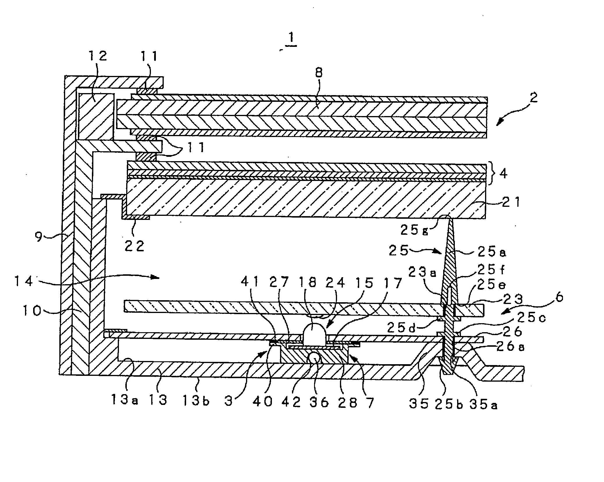
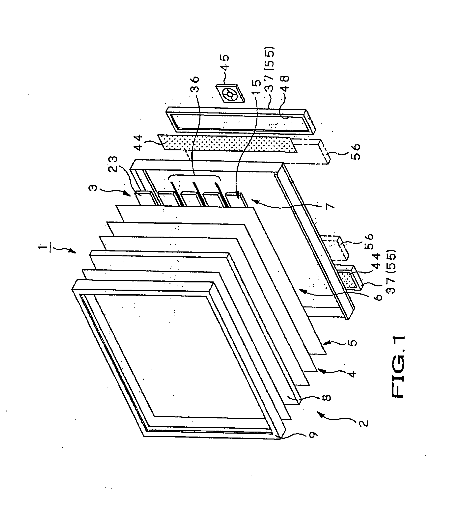
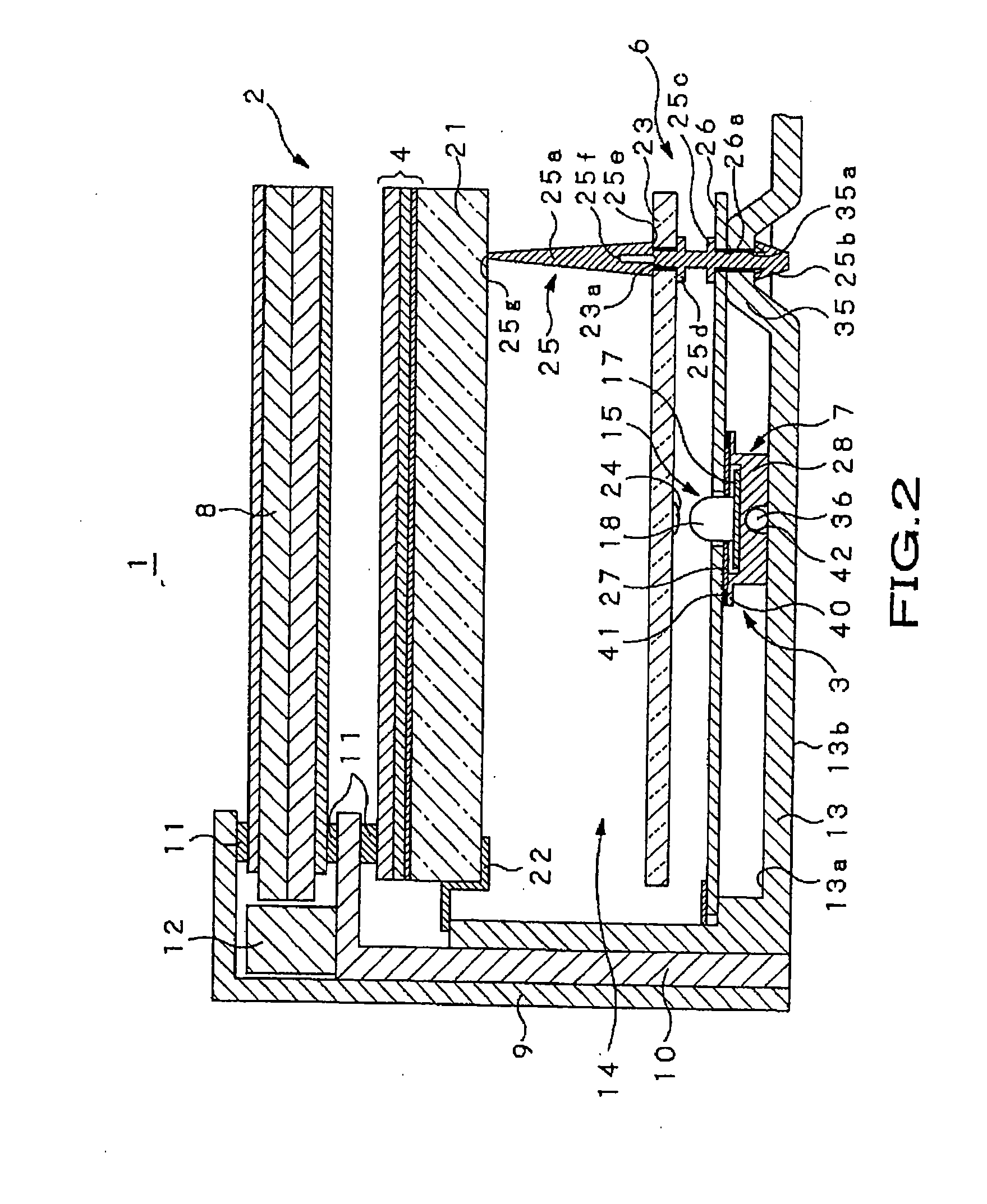
[0037] An embodiment of a transmissive liquid crystal color display unit (hereinafter referred to as LCD unit) according to the present invention will be described below in detail with reference to the accompanying drawings.

[0038] A liquid crystal display unit 1 according to the embodiment is used for a television set having a large-sized screen of, e.g., 40 inches or more, a display monitor unit, or the like. As shown in FIGS. 1 and 2, the liquid crystal display unit 1 includes a liquid crystal panel unit 2 and a backlight 3 which is mounted to the back surface side of the liquid crystal panel unit 2 and emits a large amount of illumination light. Between the liquid crystal panel unit 2 and backlight 3, an optical conversion section 4, a light guide panel 5, a reflection section 6, and a heat radiation section 7 are disposed. The optical conversion section 4 applies predetermined optical conversion to illumination light emitted from the backlight 3 so as to allow the converted lig...


PUM

PropertyMeasurementUnit
sizeaaaaaaaaaa
reflectanceaaaaaaaaaa
sizeaaaaaaaaaa

Abstract

Disclosed is a heat radiator which is provided in a transmissive display unit in which a plurality of rows of light emitting arrays constituted by arranging a plurality of light emitting units including a plurality of LEDs mounted on a wiring substrate are arranged on the back surface side of a transmissive display panel, and illuminating light emitted from the LEDs is irradiated onto the display panel. In the heat radiator, a radiation plate (28) supporting LEDs (18) and a heat sink (37) constitute an overlap area (57) with a back panel (13) interposed therebetween and are integrated with each other through the back panel by a fixing member in the overlap area. The back panel, radiation plate, and heat sink are firmly mounted to each other, achieving effective heat radiation.

Description

TECHNICAL FIELD [0001] The present invention relates to a heat radiator that effectively radiates heat generated in association with lighting operation of a transmissive display unit which is obtained by mounting a backlight unit to the back side of a transmissive display panel such as an LC (liquid crystal) panel, the backlight unit having a large number of light emitting diodes and irradiating the transmissive display panel with illumination light emitted from the light emitting diodes, and lighting operation of the light emitting diodes. [0002] This application is based upon and claims the benefit of priority from prior Japanese Patent Application No. 2004-238797, filed Aug. 18, 2004, the entire contents of which are incorporated herein by reference. BACKGROUND ART [0003] Comparing to a display unit using a CRT (Cathode-Ray tube), an LCD (Liquid Crystal Display) unit is advantageous in that its display screen has been made larger, lighter, and thinner and the power consumption th...

Claims


Application Information

Patent Timeline
Patent Type & Authority Applications(United States)
IPC IPC(8): G02F1/1333
CPCF21V29/004F21Y2101/02F21V29/74G02F2001/133628F21V29/006G02F1/133603F21V29/51F21V29/763F21Y2115/10G02F1/133628H05K7/20963H05K7/2099G02F1/1333G02F1/1335
Inventor SHIBATA, HIROKAZU
Owner SONY CORP
Why Eureka
Try Eureka