Hardened calcium phosphate cement bone implants

a calcium phosphate cement and bone implant technology, applied in the direction of prosthesis, spinal implants, coatings, etc., can solve the problems of lack of compressive strength, inability to use natural bone grafts, and high cost, and achieve the effect of reducing the cost of bone grafts

Inactive Publication Date: 2007-09-13
CALCITEC
View PDF44 Cites 50 Cited by
  • Summary
  • Abstract
  • Description
  • Claims
  • Application Information

AI Technical Summary

Benefits of technology

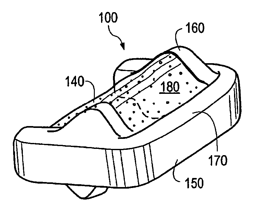
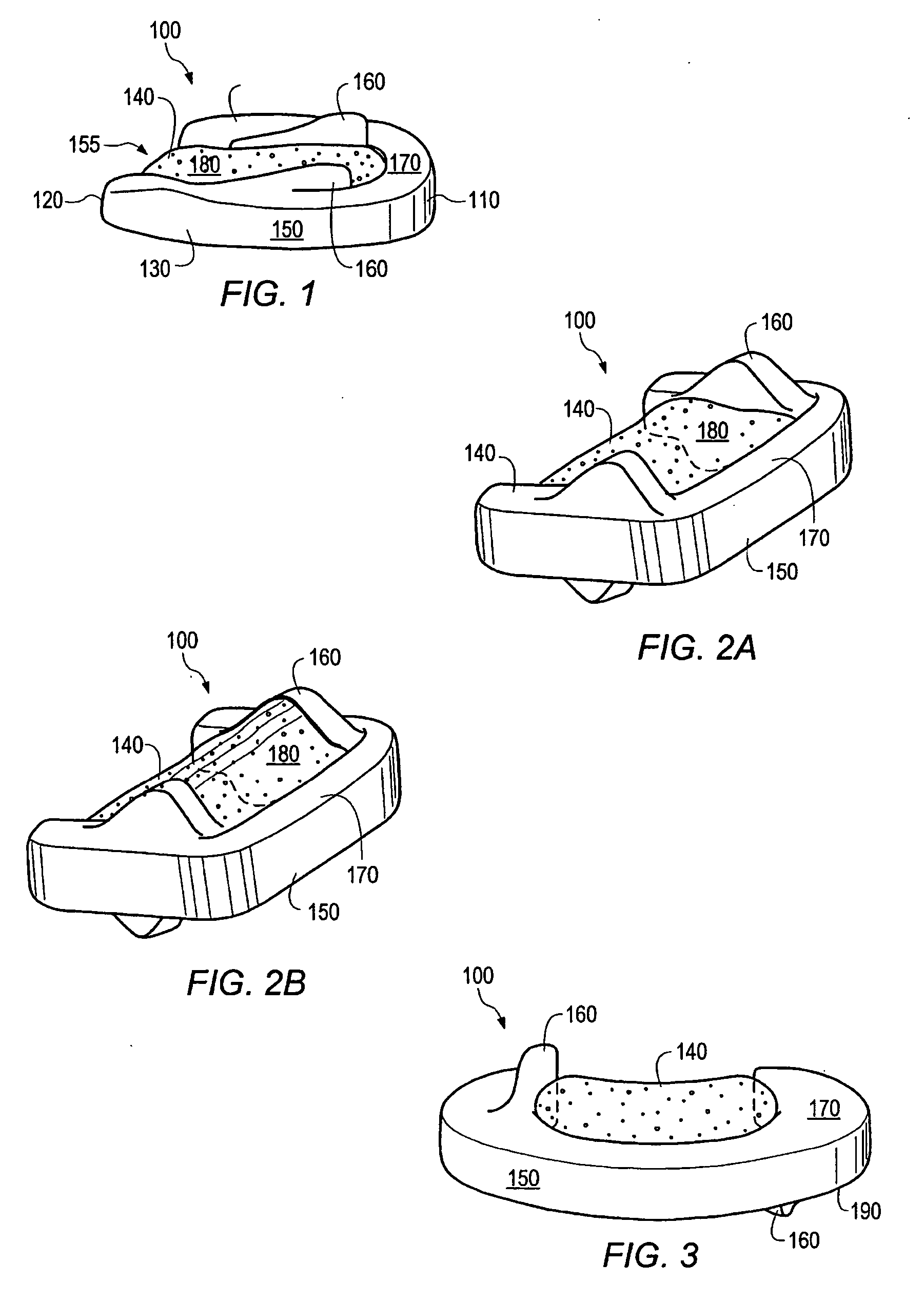
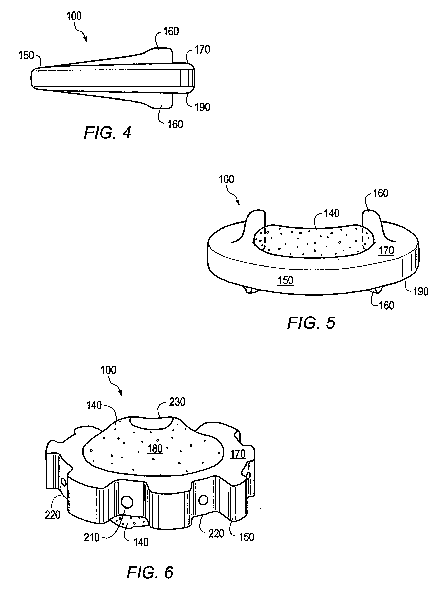
[0022] In some embodiments, a bone implant may include one or more porous components at least partially surrounded by a load bearing component. One or more porous components may have a porosity greater than the porosity of th

Problems solved by technology

However, the availability of autogenic bone and the potential of allogenic bone for initiating immunologic rejections makes the use of natural bone grafts impractical and expensive for widespread use.
The use of calcium phosphate ceramic materials, and in particular hydroxyapatite, as prosthetic implants has been hampered however, by the combined observations that unsintered calcium phosphate materials lack sufficient compressive strength and load bearing capacity to be of substantial benefit as a bone prostheses.
Additionally, sintered calcium phosphate ceramics, while able to bear higher compressive forces, are typically too brittle, and not of sufficient porosity to enable cellular and vascular in

Method used


Image

  • Hardened calcium phosphate cement bone implants
  • Hardened calcium phosphate cement bone implants
  • Hardened calcium phosphate cement bone implants

Examples


example 1

Formation of a Hardened Calcium Phosphate Cement Article

[0140] Porous calcium phosphate cement coupons were made by the following procedure. An injectable paste of calcium phosphate cement was prepared by mixing 0.6 g of whiskered TTCP powder (made according to the procedures set forth in U.S. Patent Appl. Publ. No. 2004 / 0003757) with concentrated (NH4)2HPO4 solution in water at a liquid to solid ratio of 0.3 for 1 min. The paste was then thoroughly mixed with a mixture (1:1) of NaCl and KCl salt particles (pore forming powder). The amount of salt mixed with the paste was equal to the dry weight of the salt used to make the paste. The resulting paste mixture was filled into a cylindrical stainless steel mould having a diameter of 12 mm and compressed with a gradually increased pressure up to about 45 MPa and the cement was allowed to harden. The hardened material was immersed in distilled water at 37° C. for 48 hours and dried in air for 24 hours.

Formation of a Nanocrystalline H...

example 2

[0141] The dried material made in Example 1 was immersed in Hank's balanced salt solution 1×, HyQ®HBSS cell culture reagents without Phenol Red, 0.1 μm sterile filtered; HyClone, (Logan, Utah) for 3 days, rinsed with distilled water and air dried for 24 hours.

example 3

[0142] The dried material made in Example 1 was immersed in phosphate buffered saline (PBS) for 5 days, rinsed with distilled water and then dried in air for 24 hours.

[0143] The hardened CPC discs made in Examples 2 and 3 were gold coated and the surface morphology of nanocrystalline HAp was examined using scanning electron microscopy. Representative images are shown in FIG. 1A (samples incubated in HBSS for 3 days), and FIG. 1B (sample incubated in PBS for 5 days). As shown in FIG. 1, a nanocrystalline nanoporous mineral layer was formed after the surface modification with either HBSS or PBS


PUM

PropertyMeasurementUnit
Porosityaaaaaaaaaa

Abstract

In some embodiments, an implant may include a porous component and a load bearing component at least partially surrounding the porous component. The porous component has a porosity that is greater than the porosity of the load bearing component. One or more protrusions may be present on the load bearing component. The porous component and/or a load bearing component may be at least partially composed of calcium phosphate.

Description

CROSS-REFERENCE TO RELATED APPLICATIONS [0001] This application claims the right of priority under 35 U.S.C. §119(e) to U.S. Provisional Application No. 60 / 721,299 entitled “HARDENED CALCIUM PHOSPHATE CEMENT BONE IMPLANTS” by Arramon, et al., filed Sep. 28, 2005, which is incorporated by reference in its entirety as though fully set forth herein.BACKGROUND OF THE INVENTION [0002] 1. Field of the Invention [0003] The present invention is generally relates to calcium phosphate prosthetic bone implants incorporating bioactive compositions and methods of making same. More particularly, the invention relates to the use of calcium phosphate prosthetic bone implants coated with calcium phosphate layers as delivery vehicles for bioactive compositions. [0004] 2. Description of the Relevant Art [0005] Prosthetic bone implants and bone substitute materials are commonly used in medical procedures carried out for plastic or reconstructive surgery, orthopedic or dental surgery, dental implantolog...

Claims


Application Information

Patent Timeline
IPC IPC(8): A61F2/44A61F2/28
CPCA61F2/28A61L2300/604A61F2/4455A61F2002/2817A61F2002/30011A61F2002/30014A61F2002/30062A61F2002/30113A61F2002/30115A61F2002/30125A61F2002/30131A61F2002/30677A61F2002/30772A61F2002/30878A61F2002/3092A61F2210/0004A61F2230/0006A61F2230/0008A61F2230/0013A61F2250/0018A61F2250/0023A61F2310/00293A61F2310/00353A61F2310/00796A61F2310/00976A61L27/12A61L27/32A61L27/54A61L2300/252A61L2300/402A61L2300/406A61L2300/414A61F2/30965A61L27/56A61L2430/02
Inventor ARRAMON, YVES P.
Owner CALCITEC
Why Eureka
Try Eureka