Apparatus and method for combustion

Inactive Publication Date: 2007-09-20
EVENTEMP
View PDF19 Cites 38 Cited by
  • Summary
  • Abstract
  • Description
  • Claims
  • Application Information

AI Technical Summary

Benefits of technology

[0019] From the above description, it can be understood that the burnpot of the invention and stoves that accommodate it have several advantages, such as: (1) a continuous flame may be maintained while byproducts

Problems solved by technology

The prior art systems of this type are difficult to operate automatically for long periods of time.
This approach works well with some f

Method used


Image

  • Apparatus and method for combustion
  • Apparatus and method for combustion
  • Apparatus and method for combustion

Examples


Example

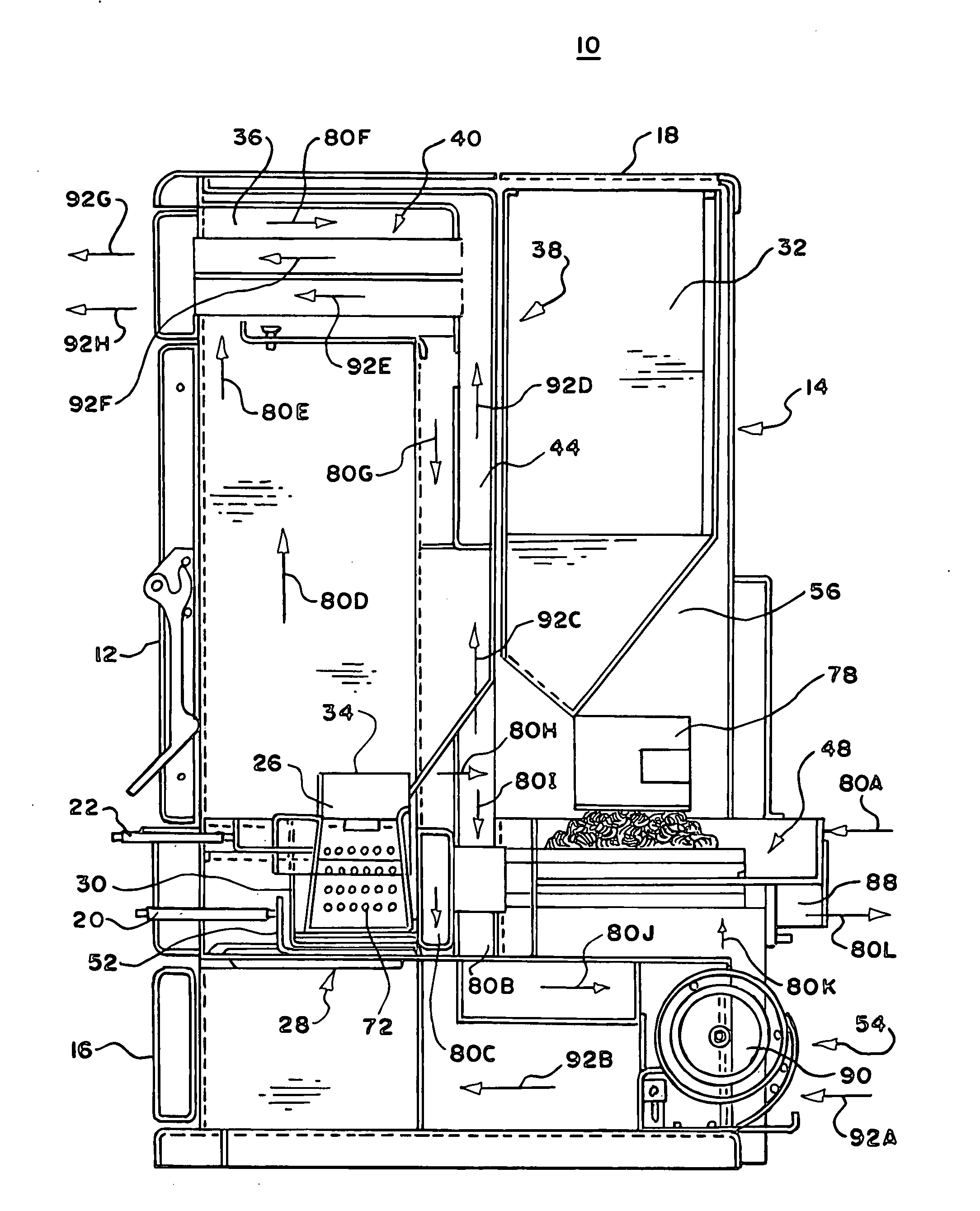
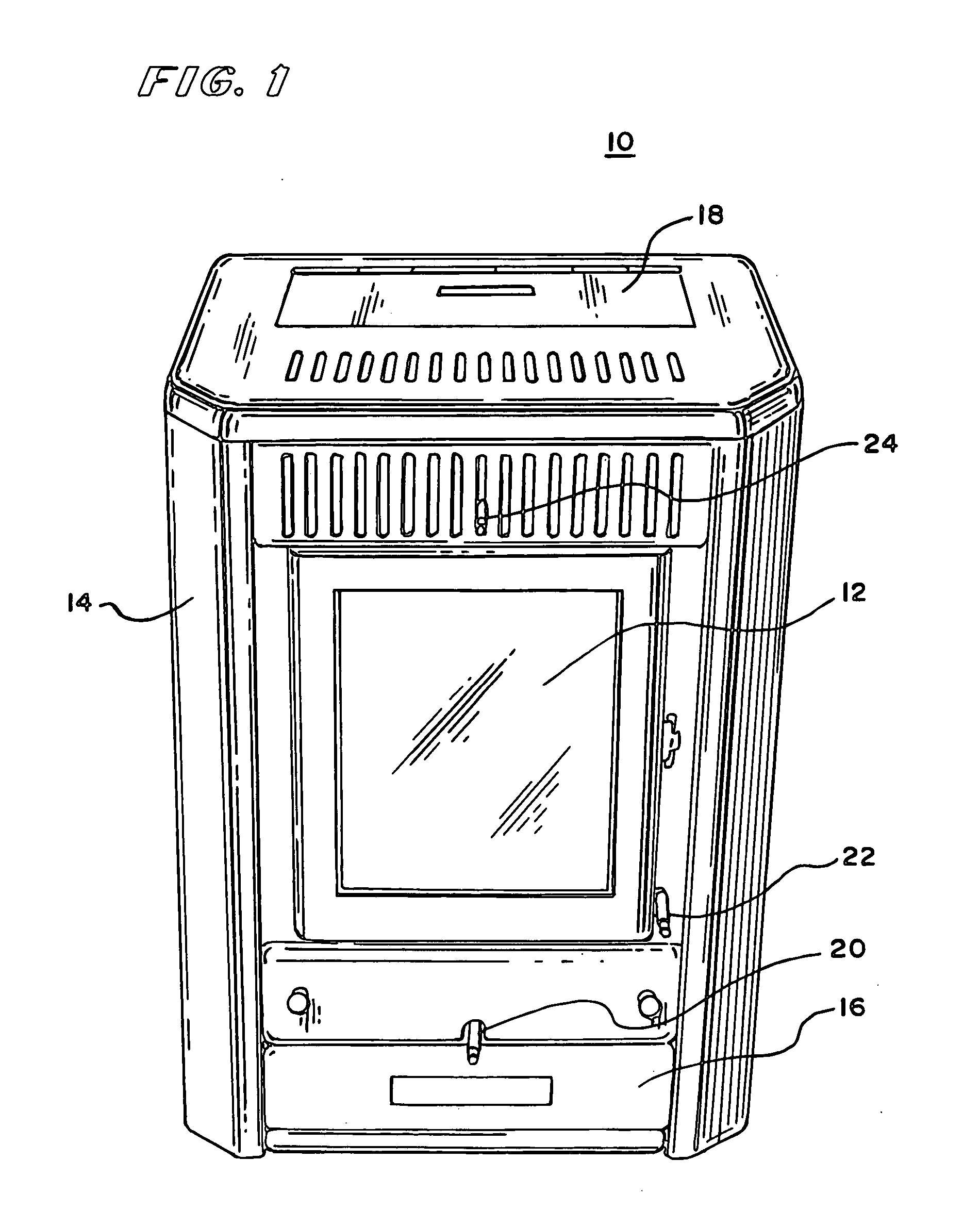
[0052] In FIG. 1, there is shown a perspective view of a burner 10, which may be for example a stove or furnace, having an enclosure 14, with an access door 12, an ash pan 16, a rod 20, a rod 22, a heat exchanger tube scraper rod 24 and a fuel hopper lid 18. The access door 12 has a transparent window through which a firebox can be seen having within it a burnpot chamber, a burnpot, a feeder system, an exhaust system, a heat exchanger system and a combustible air intake system, none of which are shown in FIG. 1. The fuel hopper in the preferred embodiment includes the hinged fuel hopper lid 18 in the top of the enclosure 14 exposing an opening through which fuel, such as for example wood pellets or corn can be poured. To permit operation of the stove or furnace 10 from outside the enclosure 14, the rod 20 is connected to an openable bottom of a burnpot (not shown in FIG. 1), the rod 22 is connected to a combustion retention slide (not shown in FIG. 1), and the heat exchanger tube sc...


PUM


Abstract

To enable a burnpot for a corn burning stove to be continuously operated, the burnpot has either: (1) an openable bottom with at least a first and second position, one of the at least first and second positions being substantially closed to enable a body of combustible fuel to burn on its upper surface, the other of the at least first and second positions providing an opening, burnpot side wall portions and a top of the burnpot being shaped so as to permit a solid clinker to drop out of the opening in the openable bottom when the openable bottom is in its second position; or (2) a bottom formed as one of a series of sections of a rotatable member so that as the member rotates, it carries ash with it away from the bottom of the burnpot. A combustion volume is provided between the openable bottom or rotatable bottom, the side surfaces and the top, the combustion volume having an upper portion and a lower portion whereby a fire on a combustion surface in the lower portion burns upwardly toward the upper portion so that byproducts of combustion build on the combustion surface to cause burning fuel to burn at a higher level; the higher level having a smaller cross sectional area than the lower portion whereby the byproducts of combustion may drop as a unit out of the burnpot bottom opening. Easy to ignite fuel is moved from one hopper into the burnpot and ignited. When the temperature is high enough to ignite the harder to ignite fuel it is moved into the burnpot and the flow of easy to ignite fuel stopped.

Description

RELATED CASES [0001] This application is a continuation-in-part of U.S. patent application Ser. No. 10 / 410,118 filed Apr. 9, 2003, and this application is a continuation-in-part of provisional patent application 60 / 779,750 filed Mar. 7, 2006, both in the name of Terry L. Krumrei. Applicant claims the benefit of the filing date of provisional patent application 60 / 779,750 filed Mar. 7, 2006.BACKGROUND OF THE INVENTION [0002] This invention relates to methods and apparatuses for combustion and more particularly to a combustion technique and equipment including a burnpot system, a fuel hopper and a method of operating the burnpot system and fuel hopper. [0003] It is known to provide a combustion system for removing ash conveniently from the bottom of a burnpot with moving walls. The prior art moving walls slide open or swing open, either completely open such as by sliding out of the bottom or partly open such as in the case of moveable grates that move back and forth to open and close....

Claims


Application Information

Patent Timeline
IPC IPC(8): F23B40/00
CPCF23B1/24F23B40/08F23N2027/02F23N5/203F23B60/02F23H15/00F23N2227/02
Inventor KRUMREI, TERRY LEE
Owner EVENTEMP
Why Eureka
Try Eureka