Stacked non-volatile memory with silicon carbide-based amorphous silicon thin film transistors

a silicon thin film transistor and silicon carbide-based amorphous technology, applied in the direction of semiconductor devices, basic electric elements, electrical equipment, etc., can solve the problems of low junction leakage current in the junction of sic substrate devices, undesirable short channel effects of transistors, random device characteristics,

Active Publication Date: 2007-09-20
MICRON TECH INC
View PDF17 Cites 257 Cited by
  • Summary
  • Abstract
  • Description
  • Claims
  • Application Information

AI Technical Summary

Benefits of technology

[0009] The above-mentioned problems with non-volatile memory performance and other problems are addressed by the present invention and will be understood by reading and studying the following specification.

Problems solved by technology

However, these transistors have undesirable short channel effects and randomness in device characteristics.
For example, in sub-75 nm feature sizes, this can result in a very large variation in device characteristics making the stacked cell approach extremely challenging for mass manufacture.
Therefore, junction leakage currents in SiC substrate devices are very low.
However, SiC substrates suffer numerous problems.
For example, wafer sizes in excess of four inches that have high quality and low cost are difficult to achieve.
Additionally, the defect densities are unacceptable and the substrates suffer from poor carrier mobility for high speed switching.

Method used


Image

  • Stacked non-volatile memory with silicon carbide-based amorphous silicon thin film transistors
  • Stacked non-volatile memory with silicon carbide-based amorphous silicon thin film transistors
  • Stacked non-volatile memory with silicon carbide-based amorphous silicon thin film transistors

Examples


Embodiment Construction

[0020] In the following detailed description of the preferred embodiments, reference is made to the accompanying drawings that form a part hereof, and in which is shown by way of illustration specific preferred embodiments in which the inventions may be practiced. These embodiments are described in sufficient detail to enable those skilled in the art to practice the invention, and it is to be understood that other embodiments may be utilized and that logical, mechanical and electrical changes may be made without departing from the spirit and scope of the present invention. The terms wafer and substrate used previously and in the following description include any base semiconductor structure. Both are to be understood as including bulk silicon, silicon-on-sapphire (SOS) technology, silicon-on-insulator (SOI) technology, silicon-on-nothing, thin film transistor (TFT) technology, doped and undoped semiconductors, epitaxial layers of silicon supported by a base semiconductor, as well as...


PUM

PropertyMeasurementUnit
sizesaaaaaaaaaa
band gap energyaaaaaaaaaa
breakdown electric fieldaaaaaaaaaa

Abstract

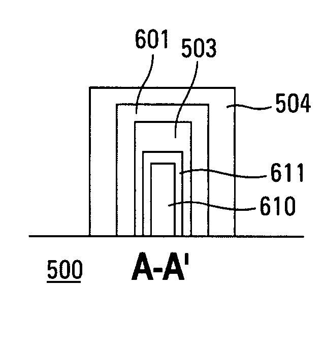
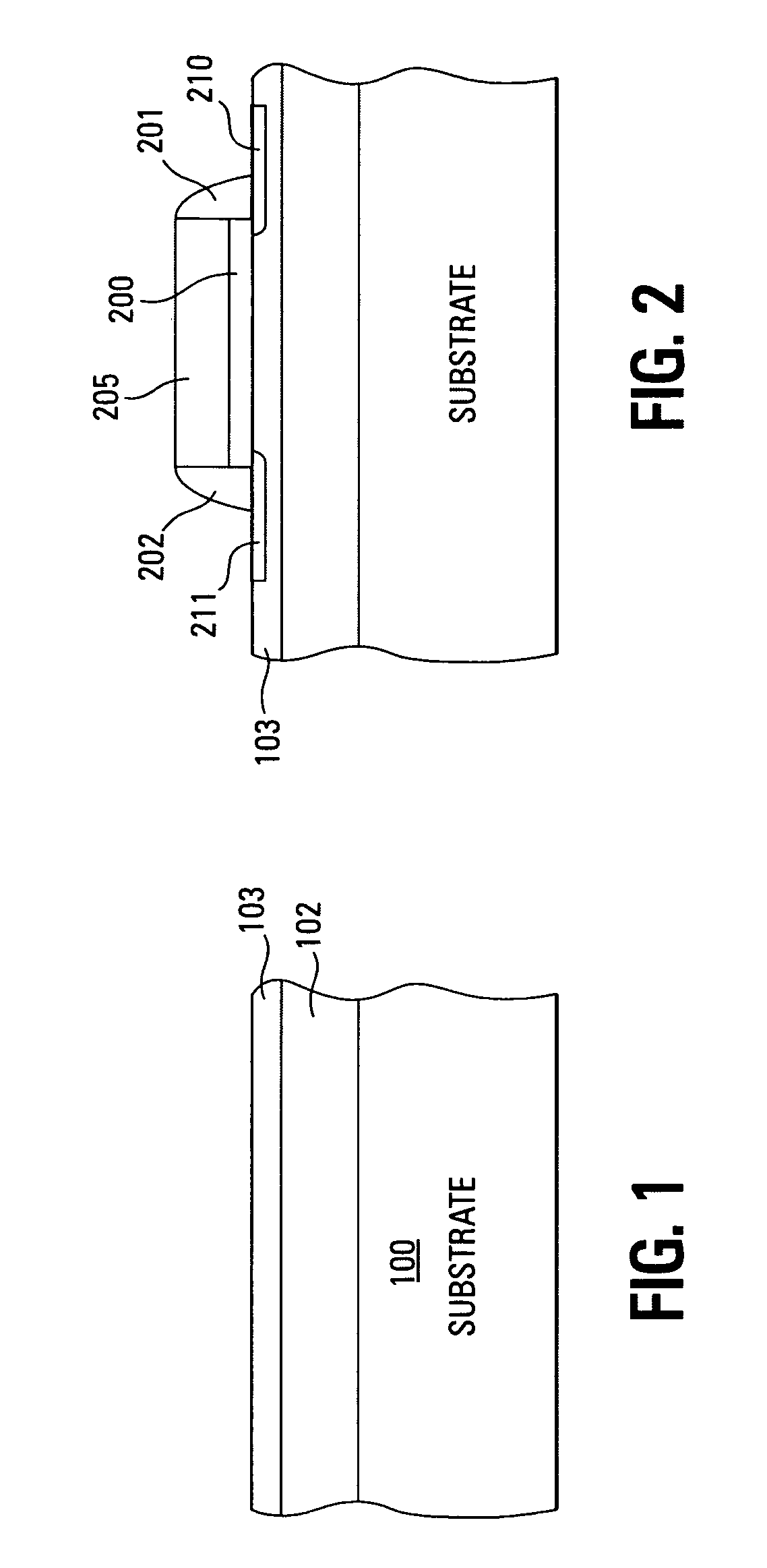
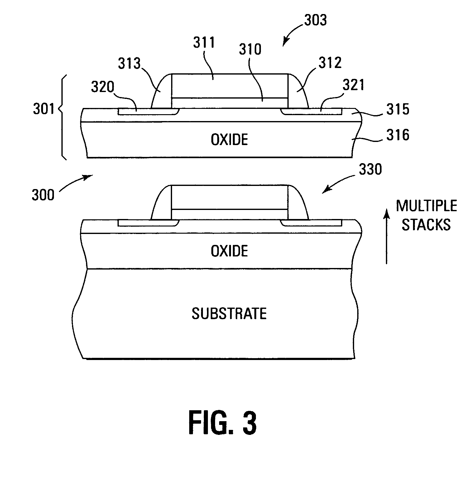
A stacked non-volatile memory device uses amorphous silicon based thin film transistors stacked vertically. Each layer of transistors or cells is formed from a deposited a-Si channel region layer having a predetermined concentration of carbon to form a carbon rich silicon film or silicon carbide film, depending on the carbon content. The dielectric stack is formed over the channel region layer. In one embodiment, the dielectric stack is an ONO structure. The control gate is formed over the dielectric stack. This structure is repeated vertically to form the stacked structure. In one embodiment, the carbon content of the channel region layer is reduced for each subsequently formed layer.

Description

TECHNICAL FIELD OF THE INVENTION [0001] The present invention relates generally to memory devices and in particular the present invention relates to non-volatile memory device architecture. BACKGROUND OF THE INVENTION [0002] Memory devices are typically provided as internal, semiconductor, integrated circuits in computers or other electronic devices. There are many different types of memory including random-access memory (RAM), read only memory (ROM), dynamic random access memory (DRAM), synchronous dynamic random access memory (SDRAM), and flash memory. [0003] Flash memory devices have developed into a popular source of non-volatile memory for a wide range of electronic applications. Flash memory devices typically use a one-transistor memory cell that allows for high memory densities, high reliability, and low power consumption. Common uses for flash memory include personal computers, personal digital assistants (PDAs), digital cameras, and cellular telephones. Program code and sys...

Claims


Application Information

Patent Timeline
Patent Type & Authority Applications(United States)
IPC IPC(8): H01L29/76
CPCH01L21/84H01L27/115H01L27/11568H01L27/11578H01L29/1608H01L29/66068H01L27/11551H01L29/785H01L29/792H01L29/66795H01L21/02529H01L21/3148H01L29/66833H10B69/00H10B43/20H10B43/30H01L29/78645H10B41/20
Inventor MOULI, CHANDRA
Owner MICRON TECH INC
Why Eureka
Try Eureka