

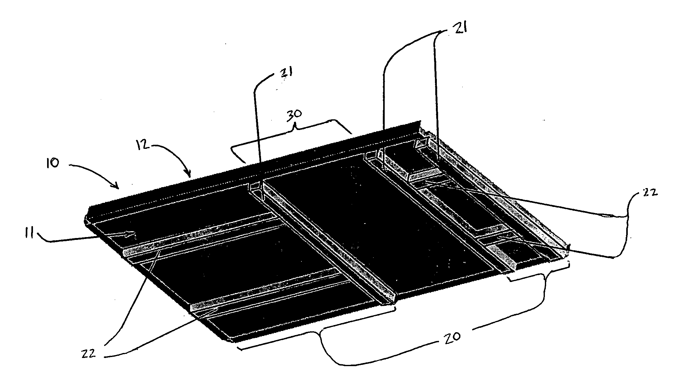
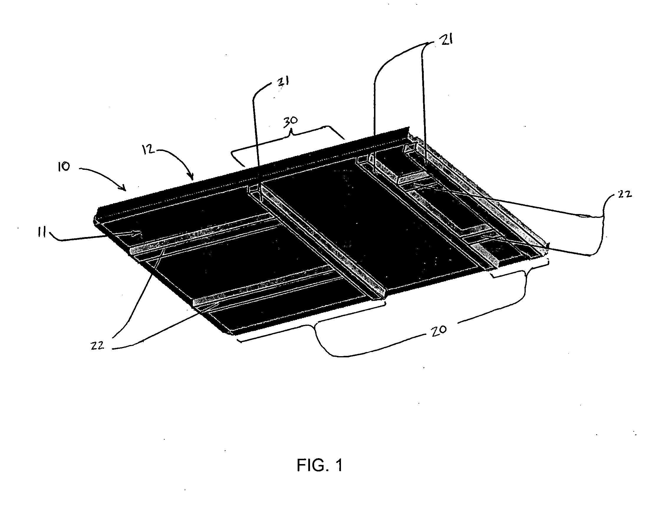
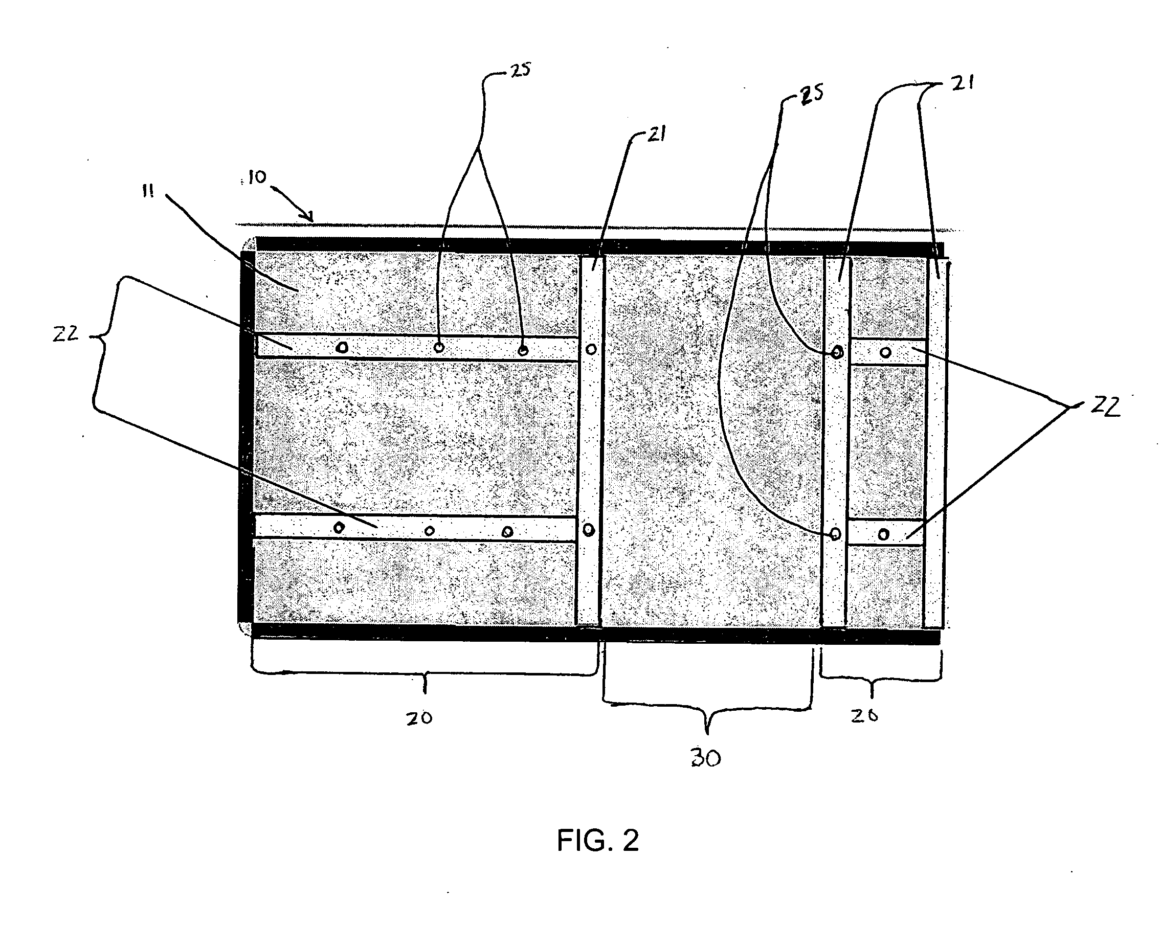
Composite cargo floor structure having a reduced weight
a cargo floor and cargo technology, applied in the direction of monocoque constructions, superstructure subunits, loading-carrying vehicle superstructures, etc., can solve the problems of reducing the effective cargo capacity reducing fuel economy, and adding to the empty weight of the cargo vehicle, so as to achieve enhanced load-bearing capacity and reduce weight
- Summary
- Abstract
- Description
- Claims
- Application Information
AI Technical Summary
Benefits of technology
Problems solved by technology
Method used
Image

Examples
Embodiment Construction
[0017] The present inventions now will be described more fully hereinafter with reference to the accompanying drawings, in which some, but not all embodiments of the inventions are shown. Indeed, these inventions may be embodied in many different forms and should not be construed as limited to the embodiments set forth herein; rather, these embodiments are provided so that this disclosure will satisfy applicable legal requirements. Like numbers refer to like elements throughout. The singular forms “a,”“an,” and “the” include plural referents unless the context clearly dictates otherwise.
[0018] Although the preferred embodiments of the invention described herein are directed to a composite cargo floor assembly for attachment to a truck body, it will be appreciated by one skilled in the art that the invention is not so limited. For example, embodiments of the composite cargo floor assembly of the present invention can also be incorporated into various other types of cargo vehicles in...
PUM
 Abstract
Description
Claims
Application Information