Brake by wire type brake system

a brake system and wire technology, applied in the direction of braking systems, braking components, electronic commutators, etc., can solve the problems of increasing reducing the operational responsiveness of the fluid pressure generator, increasing heat generation, etc., to increase the rotational speed of the electric motor, improve the operational responsiveness, and increase the size of the electric motor

Inactive Publication Date: 2007-09-20
HONDA MOTOR CO LTD
View PDF15 Cites 13 Cited by
  • Summary
  • Abstract
  • Description
  • Claims
  • Application Information

AI Technical Summary

Benefits of technology

[0009]The present invention has been achieved in view of the above circumstances, and has an object to improve operational responsiveness by increasing a rotational speed of an electric motor of an actuator of a BBW type brake system as necessary, without increasing the size of the electric motor.

Problems solved by technology

However, it is known that the unit characteristics of the electric motor used as the drive source of the fluid pressure generator of such a BBW type brake system are determined during the design phase, and that the rated torque becomes low when the rated rotational speed is set to be high, while the rated rotational speed becomes low when the rated torque is set to be high.
However, since the number of windings of the winding wire is required to be large, there arises a problem of increase in the size of the electric motor.
In addition, the rotational speed becomes low, leading to reduced operational responsiveness of the fluid pressure generator.
However, when large torque is to be generated, a large motor current is required, causing a problem of increased heat generation.
Then, in order to decrease the motor current, it is conceivable to increase the reduction ratio of the speed reducer, but in this case, there arises a problem that the size of the fluid pressure generator becomes large which makes it more difficult to mount it to a vehicle.

Method used


Image

  • Brake by wire type brake system
  • Brake by wire type brake system
  • Brake by wire type brake system

Examples


Embodiment Construction

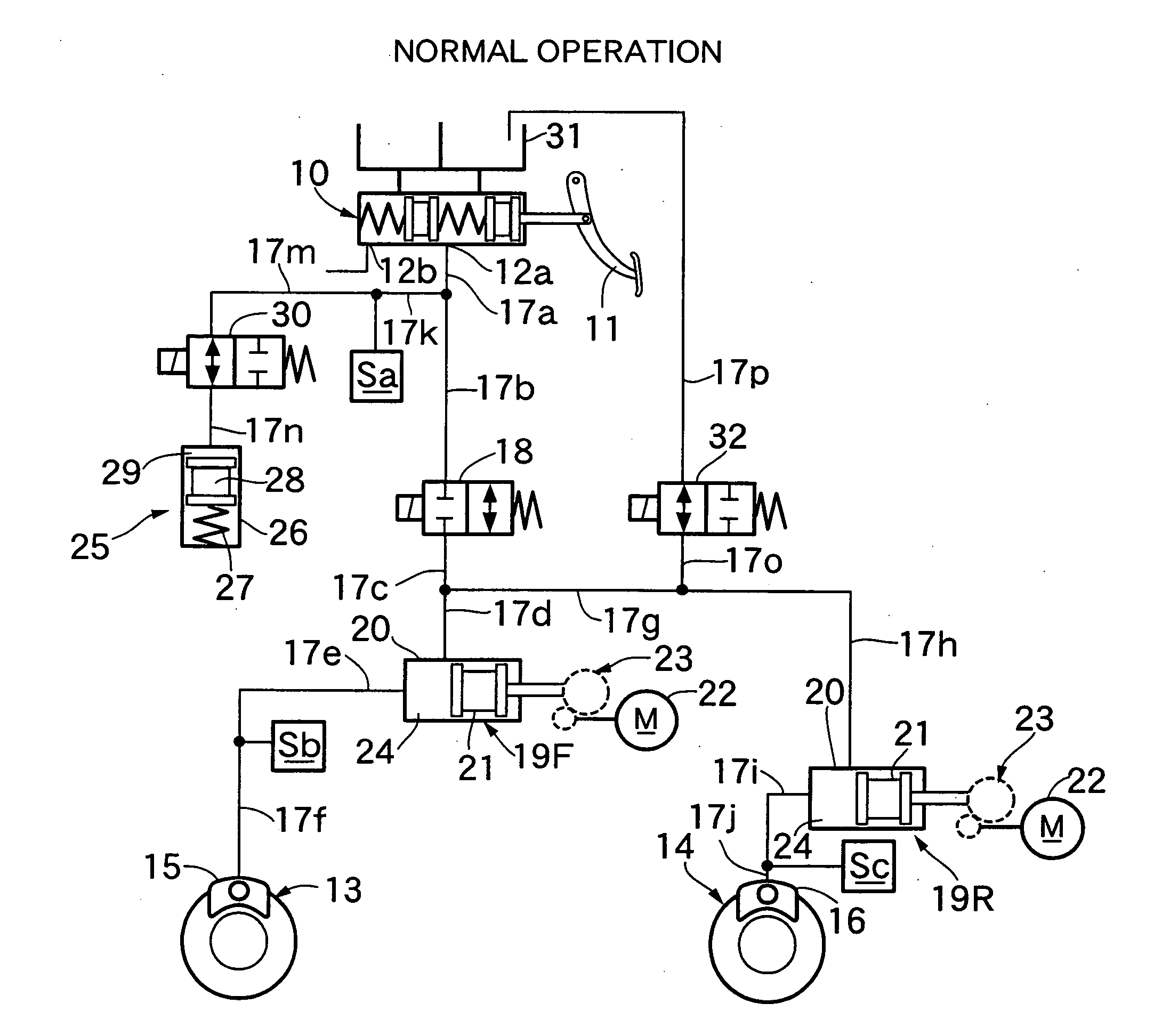
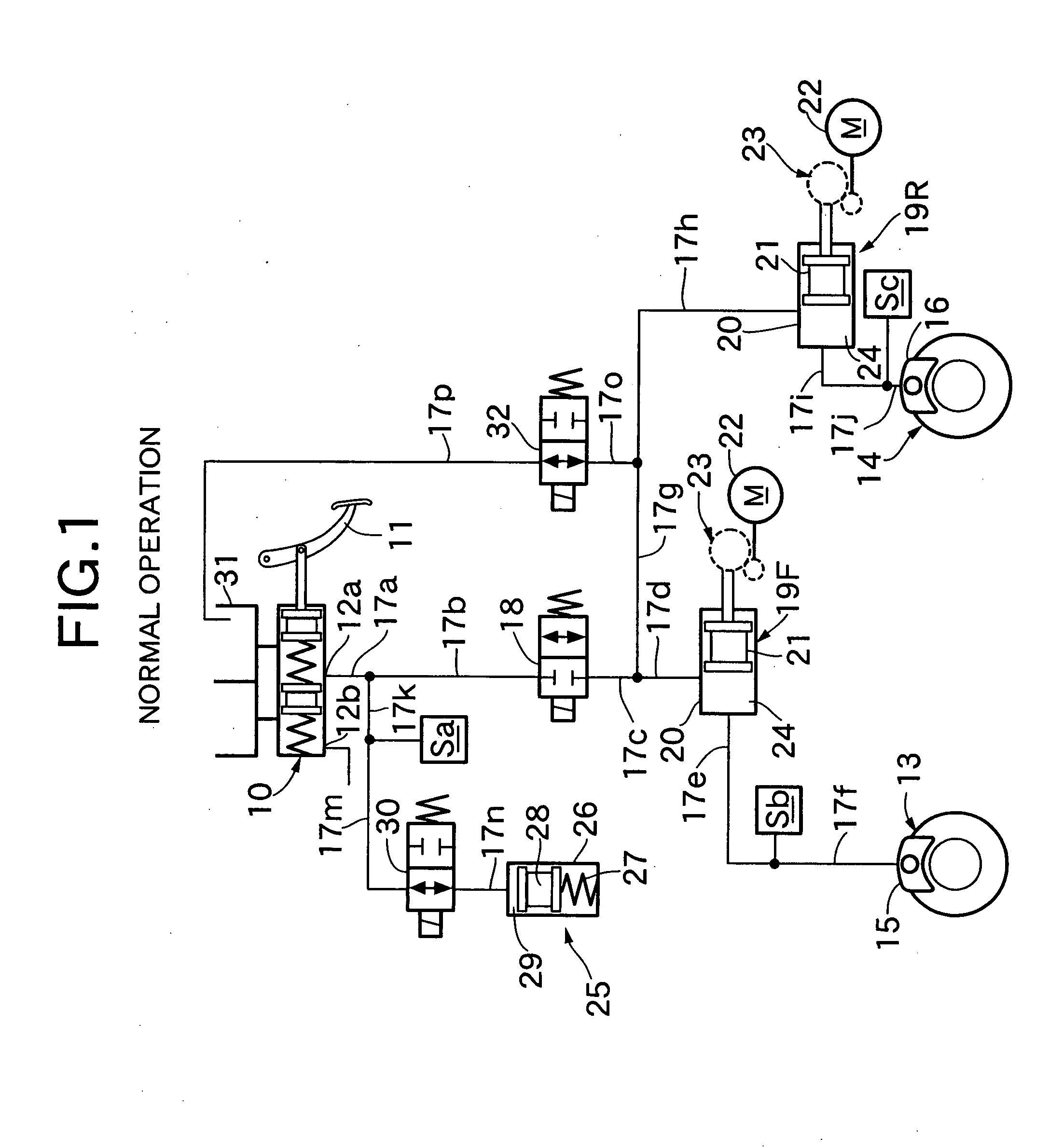
[0028]As shown in FIG. 1, a tandem type master cylinder 10 includes first and second output ports 12a and 12b which output brake fluid pressure corresponding to the stepping force with which a driver depresses a brake pedal 11. The first output port 12a is connected to disc brake devices 13 and 14 of a left front wheel and a right rear wheel, for example, and the second output port 12b is connected to disc brake devices at a right front wheel and a left rear wheel, for example. FIG. 1 shows only one brake system which connects to the first output port 12a, and does not show the other brake system which connects to the second output port 12b, but the structures of the one and other brake systems are substantially the same. The one brake system which connects to the first output port 12a will be described below.

[0029]The first output port 12a of the master cylinder 10 and a wheel cylinder 15 of the disc brake device 13 of the front wheel are connected with fluid passages 17a to 17f. F...


PUM


Abstract

A BBW type brake system which operates fluid pressure generators having electric motors as drive sources based on an electrical signal to brake a wheel, field weakening control of the electric motors is performed in the initial stage of operation of the fluid pressure generators to increase the rotational speed of the electric motors. Therefore, it is possible to reduce a time lag before the braking force actually generates after the electrical signal for operating the fluid pressure generators is outputted, thereby improving operational responsiveness. After the braking force actually generates, the field weakening control is cancelled to secure a required braking force with a sufficient torque.

Description

CROSS-REFERENCE TO RELATED APPLICATIONS[0001]The present invention claims priority under 35 USC 119 based on Japanese patent application No. 2006-069560, filed on Mar. 14, 2006. The entirety of the subject matter of this priority document is incorporated by reference herein.BACKGROUND OF THE INVENTION[0002]1. Field of the Invention[0003]The present invention relates to a brake by wire (BBW) type brake system which outputs an electrical signal corresponding to an operation amount of a brake operating element operated by a driver. An actuator, having an electric motor as a drive source, operates based on the electrical signal to brake a wheel.[0004]2. Description of the Related Art[0005]Japanese Patent Application Laid-open No. 2000-127805 discloses a so-called BBW type brake system which operates a fluid pressure brake with brake fluid pressure generated by a power fluid pressure source when communication between a master cylinder that generates brake fluid pressure by a driver depre...

Claims


Application Information

Patent Timeline
Patent Type & Authority Applications(United States)
IPC IPC(8): B60T13/00B60T8/17H02P6/06H02P6/08H02P6/17H02P6/28
CPCB60T8/4081B60T7/042
Inventor MATSUSHITA, SATOSHIHATANO, KUNIMICHI
Owner HONDA MOTOR CO LTD
Why Eureka
Try Eureka