Electric power supply system and electric power supply system for motor vehicle

Inactive Publication Date: 2007-09-20
SEMICON ENERGY LAB CO LTD
View PDF11 Cites 104 Cited by
  • Summary
  • Abstract
  • Description
  • Claims
  • Application Information

AI Technical Summary

Benefits of technology

[0005]However, the frequency of usage of movable electronic devices such as portable telephones and digital video cameras has risen steadily, and there is a limit to improving the durability and reducing the power consumption of batteries for coping with the operating time. Further, for charging batteries which are a power source that are built into portable telephones, digital video cameras, and the like, there have not been any methods other than charging from a charger through an AC adaptor via a household alternating current power supply or from a commercially available primary cell. Therefore, charging has been troublesome for users, and it has been necessary for users to take an AC adaptor or a primary cell which is a power supply means with them when they are moving about outdoors, which is burdensome.
[0008]Therefore, an object of the invention is to provide for a movable electronic device a power receiving device that simplifies charging a battery, which is a charging means, from a power feeder, which is a power supply means, and in which there is no possibility of malfunctions occurring due to an external factor relating to the relay terminal for directly connecting the battery and the power supply means, and no possibility of damage to the relay terminal itself. Further, an object of the invention is to provide an electronic device including the power receiving device.
[0019]A power receiving device of the invention includes an antenna circuit. Therefore, it is not necessary to provide a relay terminal as a portion which conducts electricity to a battery in a movable electronic device, and power can be supplied to the battery by a radio signal without malfunctions caused by damage to or defects in a relay terminal. In addition, since a power supply means for conducting power supply supplies power to a movable electronic device having a battery that is a charging device via a radio signal, charging can be conducted anytime, without the need for carrying a charger or a primary cell for charging.

Problems solved by technology

However, the frequency of usage of movable electronic devices such as portable telephones and digital video cameras has risen steadily, and there is a limit to improving the durability and reducing the power consumption of batteries for coping with the operating time.
Further, for charging batteries which are a power source that are built into portable telephones, digital video cameras, and the like, there have not been any methods other than charging from a charger through an AC adaptor via a household alternating current power supply or from a commercially available primary cell.
Therefore, charging has been troublesome for users, and it has been necessary for users to take an AC adaptor or a primary cell which is a power supply means with them when they are moving about outdoors, which is burdensome.
However, ignition of a spark plug by electric power charged to a battery is required to start up the combustion engine.
Therefore, when the battery has ‘gone flat’ due to the motor vehicle not being used for a certain period of time, ignition of the spark plug cannot be conducted, and to start up the combustion engine it is necessary to conduct electric power supply directly from outside the vehicle using a cable, which is a problem in terms of safety and convenience.
Accordingly, there has been a problem in that malfunctions occur when the relay terminal is damaged or defective.

Method used


Image

  • Electric power supply system and electric power supply system for motor vehicle
  • Electric power supply system and electric power supply system for motor vehicle
  • Electric power supply system and electric power supply system for motor vehicle

Examples


embodiment modes

[0049]Hereinafter, embodiment modes of the invention will be described with reference to the accompanying drawings. However, the invention can be carried out in many different modes, and those skilled in the art will appreciate that a variety of modifications can be made to the embodiment modes and their details without departing from the spirit and scope of the invention. Accordingly, the invention should not be construed as being limited to the description of the embodiment modes below. Note that in the following description of structures of the invention, like reference numerals are used to indicate like parts in the drawings.

embodiment mode 1

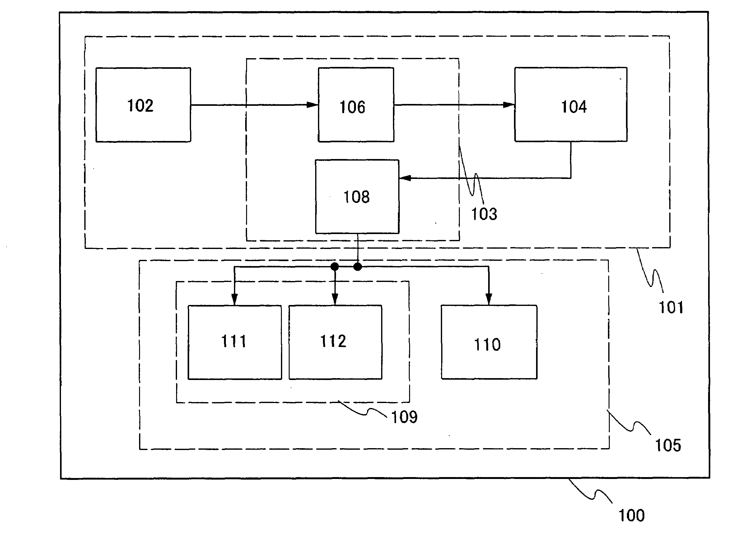
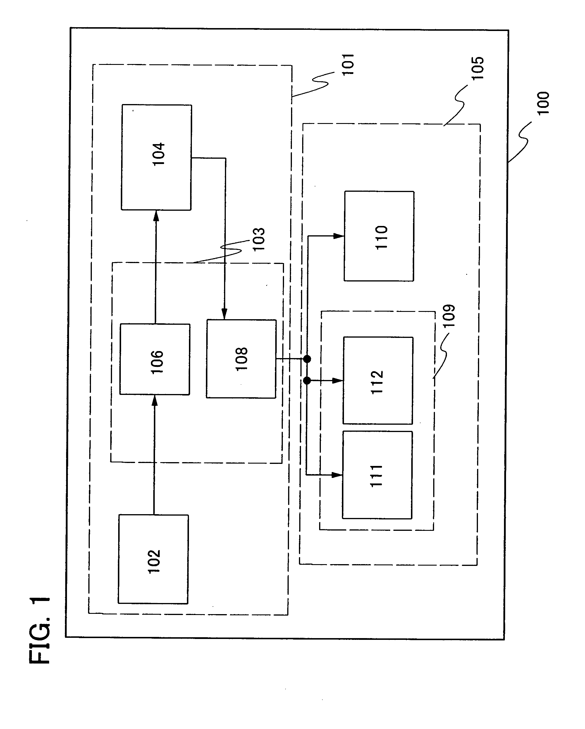
[0050]A structure of a movable electronic device having a power receiving device of the invention will be described, with reference to the block diagrams of FIGS. 1 and 2.

[0051]A movable electronic device 100 in FIG. 1 includes a power receiving device portion 101 and a power supply load portion 105. The power receiving device portion 101 includes an antenna circuit 102, a signal processing circuit 103, and a battery 104. The signal processing circuit 103 includes a rectifier circuit 106 and a power supply circuit 108.

[0052]Note that the power supply circuit 108 in FIG. 1 supplies electric power to the power supply load portion 105. However, since the configuration of the power supply load portion 105 differs from movable electronic device to movable electronic device, in this embodiment mode, a case where the configuration is that of a portable telephone or a digital video camera is described. Accordingly, the power supply circuit 108 supplies power to a display portion 109 and an ...

embodiment mode 2

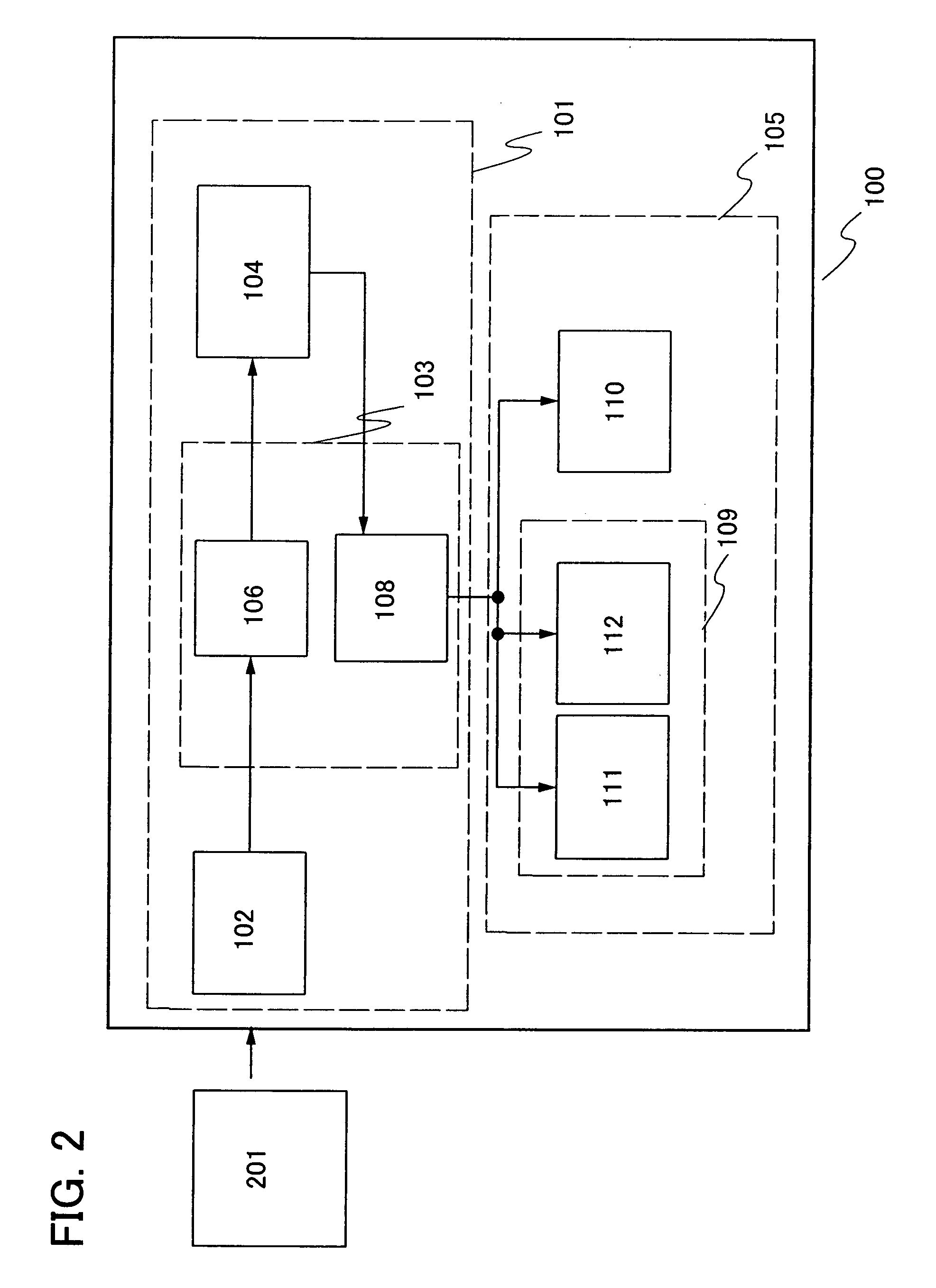
[0069]In this embodiment mode, a structure in which a booster antenna circuit (hereinafter referred to as a booster antenna) is included in the structure of the movable electronic device equipped with a power receiving device shown in Embodiment Mode 1 is explained, with reference to drawings. Note that in the drawings used in this embodiment mode, for parts that are the same as those in Embodiment Mode 1, the same numbers as those in Embodiment Mode 1 are used.

[0070]Note that the booster antenna described in this embodiment mode refers to an antenna having a larger size than that of the antenna provided in the power receiving device which receives signals from the power feeder. The booster antenna refers to an antenna that can efficiently transmit a signal that is supplied from the power feeder to the destination of the signal, the power receiving device, by resonating the signal from the power feeder at a frequency band that is used and magnetically coupling the antenna circuit pr...


PUM


Abstract

To provide for a movable electronic device a power receiving device that when charging a battery, simplifies charging of the battery from a power feeder, which is a power supply means, and does not have faults due to an external factor relating to a relay terminal, or damage of the relay terminal, that are caused by directly connecting the battery and the power feeder, and further, to provide an electronic device including the power receiving device. An antenna circuit and a booster antenna for supplying electric power are provided in a movable electronic device. The antenna circuit receives a radio signal such as an electromagnetic wave via the booster antenna, and electric power that is obtained through the receiving of the radio signal is supplied to the battery through a signal processing circuit.

Description

TECHNICAL FIELD[0001]The present invention relates to power receiving devices. In particular, the invention relates to power receiving devices that receive electric power via radio waves. Further, the invention relates to a power receiving device having an antenna for receiving electric power through radio waves, and to an electric power supply system using a power feeder having an antenna for supplying electric power to the power receiving device via radio waves.[0002]Note that ‘power receiving device’ as referred to in this specification means devices in general which receive electric power supply via a radio signal, from an externally located electric power supply device.BACKGROUND ART[0003]Various electric appliances are coming into wide use and a wide variety of appliances are on the market. In particular, in recent years the spread of portable electronic devices has been marked. As an example, portable telephones, digital video cameras, and the like, have become very convenien...

Claims


Application Information

Patent Timeline
IPC IPC(8): H02J7/00H01M10/44H02J50/00H02J50/12H02J50/70H04M1/02
CPCB60L8/003B60L11/182B60L2230/16H02J7/0052H02J7/025H02J17/00Y02T90/163Y02T10/7011Y02T10/7083Y02T10/7088Y02T90/122Y02T90/128Y02T90/14Y02T10/7005B60L53/12B60L53/305H02J50/10H02J50/12H02J50/20H02J50/27Y02T90/16Y02T10/70Y02T10/7072Y02T90/12H02J50/402H02J50/005H02J50/70H02J7/0013H02J50/90H02J7/00
Inventor SHIONOIRI, YUTAKAKOYAMA, JUNKUROKAWA, YOSHIYUKIYAMAZAKI, SHUNPEIIKEDA, TAKAYUKIOSADA, TAKESHIATSUMI, TOMOAKIISHII, MASATO
Owner SEMICON ENERGY LAB CO LTD
Why Eureka
Try Eureka