
Method, System And Apparatus For Controlled Impedance At Transitional Plated-Through Hole Via Sites Using Barrel Inductance Minimization

a barrel inductance and impedance minimization technology, applied in the direction of printed element electric connection formation, high frequency circuit adaptation, printed circuit non-printed electric component association, etc., can solve the problems of low impedance stability, low control impedance, signal integrity and electromagnetic interference, etc., to reduce radiated magnetic emission and improve control impedance

Inactive Publication Date: 2007-09-20
DELL PROD LP
View PDF9 Cites 12 Cited by
  • Summary
  • Abstract
  • Description
  • Claims
  • Application Information

AI Technical Summary

Benefits of technology

This approach enhances signal integrity and reduces electromagnetic interference by matching the electrical characteristics of inner-via traces with surface traces, providing flexible substrate configurations suitable for various electronic components and devices.

Problems solved by technology

In general, impedance discontinuities give rise to a host of signal integrity and electromagnetic interference issues included among which are reflection, noise voltage margin violations, jitter, etc.
However, many have limitations such as cost, manufacturing challenges, electrical-benefit uncertainties, etc.
Among the techniques mentioned in the literature, such techniques are either sparsely used in other industries or include approaches developed with minimal or no benefit.
One limitation of back drilling plated through-hole vias is that the process is typically restricted to printed circuit boards whose thicknesses are greater than one-hundred-twenty to one-hundred thirty (120-130) mils.
This limitation is even more significant in the area of computer designs where laptops, work stations and servers typically possess printed circuit boards having a thickness no greater than eighty-five (85) mils.

Method used


Image

  • Method, System And Apparatus For Controlled Impedance At Transitional Plated-Through Hole Via Sites Using Barrel Inductance Minimization
  • Method, System And Apparatus For Controlled Impedance At Transitional Plated-Through Hole Via Sites Using Barrel Inductance Minimization
  • Method, System And Apparatus For Controlled Impedance At Transitional Plated-Through Hole Via Sites Using Barrel Inductance Minimization

Examples


Embodiment Construction

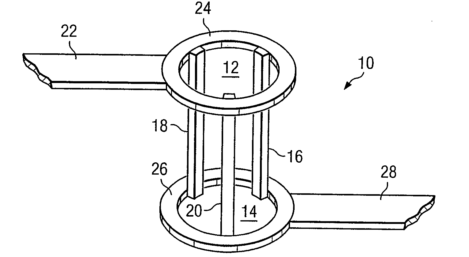
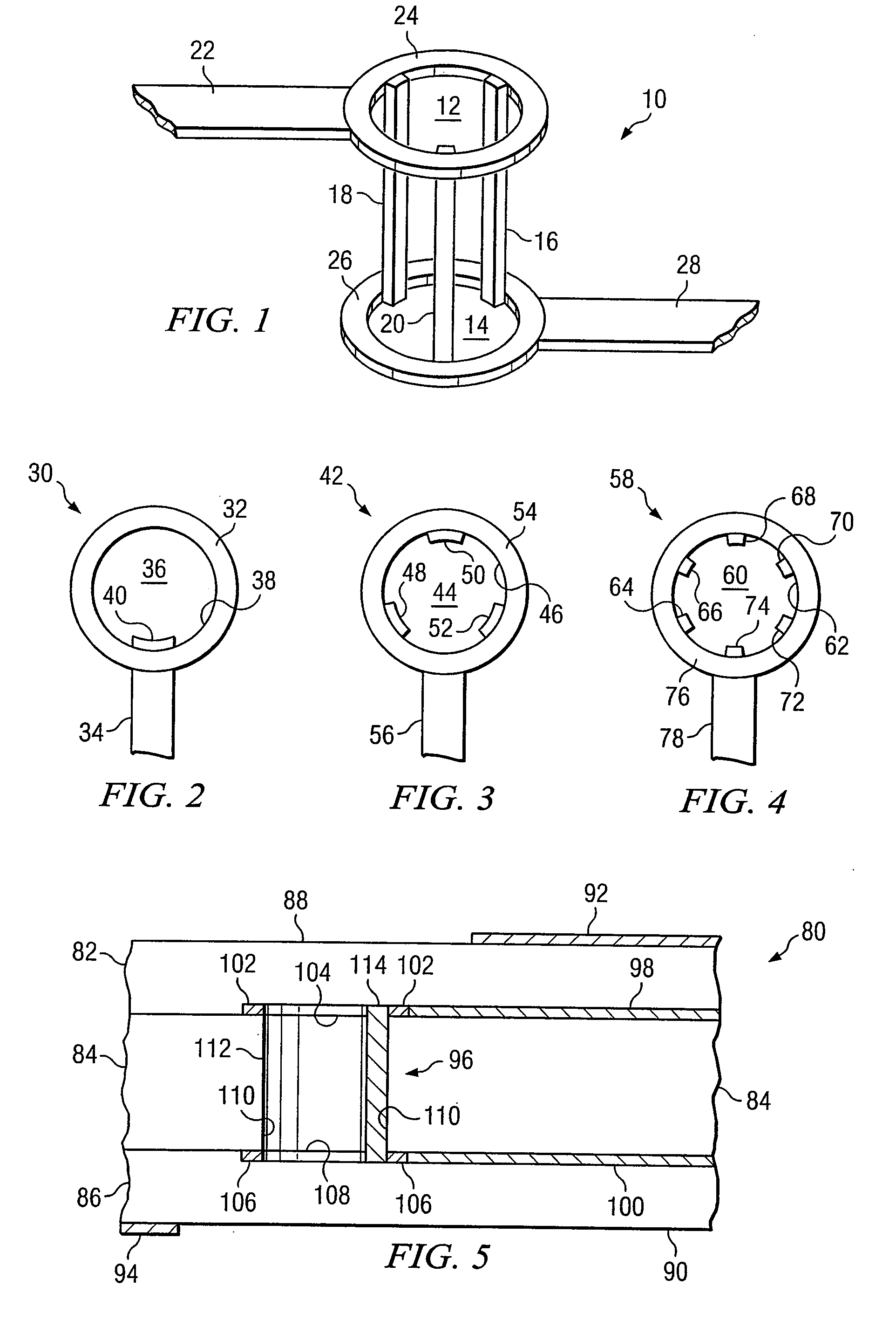
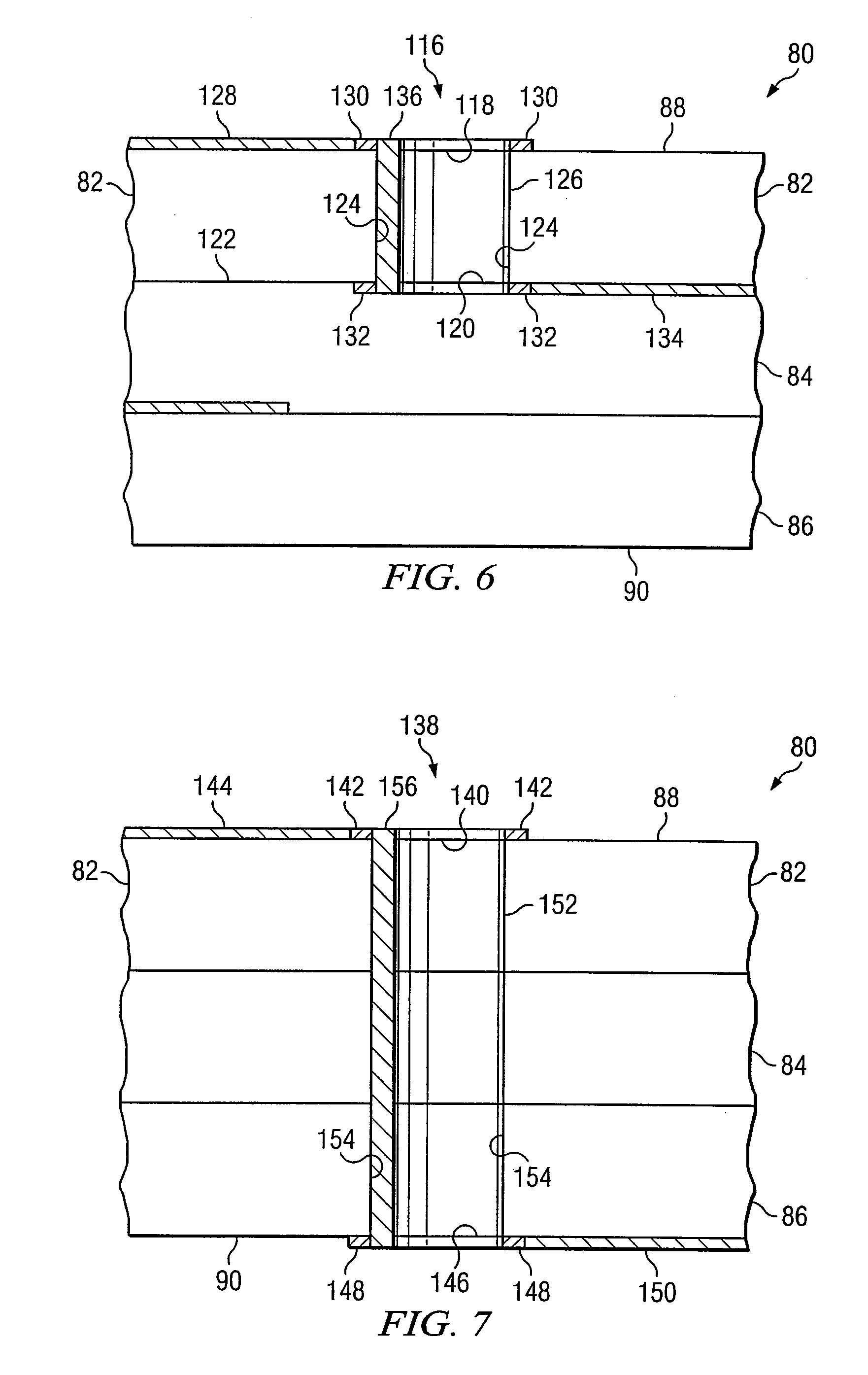
[0021] Preferred embodiments and their advantages are best understood by reference to FIGS. 1 through 7, wherein like numbers are used to indicate like and corresponding parts.

[0022] For purposes of this disclosure, an information handling system may include any instrumentality or aggregate of instrumentalities operable to compute, classify, process, transmit, receive, retrieve, originate, switch, store, display, manifest, detect, record, reproduce, handle, or utilize any form of information, intelligence, or data for business, scientific, control, or other purposes. For example, an information handling system may be a personal computer, a network storage device, or any other suitable device and may vary in size, shape, performance, functionality, and price. The information handling system may include random access memory (RAM), one or more processing resources such as a central processing unit (CPU) or hardware or software control logic, ROM, and / or other types of nonvolatile memo...


PUM

PropertyMeasurementUnit
thicknessesaaaaaaaaaa
thicknessaaaaaaaaaa
conductiveaaaaaaaaaa

Abstract

A system, apparatus and method for controlled impedance at transitional via sites using barrel inductance minimization are provided. In one embodiment, one or more sidewalls of a via barrel are preferably processed such that conductive material disposed thereon is selectively removed thereby forming an inner-via trace connecting one or more conductive traces and / or pads on a first substrate layer to one or more conductive traces and / or pads on a second substrate layer. Removal of conductive material from a sidewall of the via barrel is done in a manner such that an inner-via trace traveling from a first surface to a second surface of one or more substrate layers possesses at least one electrical characteristic substantially approximating a corresponding electrical characteristic of those structures to which the inner-via trace is connected.

Description

TECHNICAL FIELD [0001] The present invention relates generally to information handling systems and, more particularly, to the structure and fabrication of component substrates. BACKGROUND OF THE DISCLOSURE [0002] As the value and use of information continues to increase, individuals and businesses seek additional ways to process and store information. One option available to users is information handling systems. An information handling system generally processes, compiles, stores, and / or communicates information or data for business, personal, or other purposes thereby allowing users to take advantage of the value of the information. Because technology and information handling needs and requirements vary between different users or applications, information handling systems may also vary regarding what information is handled, how the information is handled, how much information is processed, stored, or communicated, and how quickly and efficiently the information may be processed, s...

Claims


Application Information

Patent Timeline
Patent Type & Authority Applications(United States)
IPC IPC(8): H05K7/06H05K1/02H05K1/11H05K3/42
CPCH05K1/0237H05K1/115Y10T29/49124H05K2201/09536H05K2201/09645H05K3/429
Inventor MASUYAMA, JINSAKUMURUGAN, RAJEN
Owner DELL PROD LP
Learn More