[0012]An object of the present invention is to provide (i) an external belt heat fixing apparatus which suppresses (a) heat damage to the endless belt and the surface of the fixing member and (b) unevenness of an image, and (ii) an image forming apparatus including the fixing apparatus.
[0015]In a situation where the equation (1) is satisfied, rise in temperature of the support rollers is suppressed even when heat of the heating means is transferred to the support rollers after the completion of the fixing (when the rotation of the fixing member is stopped) and at the time of paper jam. As a result, it is possible to suppress local rise in temperature of the endless belt and the fixing member. Thus, it is possible to suppress degradation due to temperatures of the surfaces of the endless belt and the fixing member, and to reduce unevenness of the image.
[0017]In a situation where the equation (2) is satisfied, it is possible to suppress the difference in temperature between the belt suspending rollers and the endless belt to not more than approximately 20° C. Further, in a situation where the equation (2) is satisfied, rise in temperature of the endless belt is suppressed even when heat of the heating means is transferred to the support rollers after the completion of the fixing (when the rotation of the fixing member is stopped) and at the time of paper jam. As a result, it is possible to suppress local rise in temperature of the fixing member. Thus, it is possible to suppress degradation due to temperatures of the surfaces of the endless belt and the fixing member, and to reduce unevenness of the image. Still further, in a situation where the equation (2) is satisfied, it was confirmed that degradation due to temperatures of the surfaces of the endless belt and the fixing member was not found and it was possible to reduce unevenness of the image.
[0020]It is clear from the experiment that it is possible to suppress the difference in temperature between the surface of the endless belt and the surface of the fixing member to not more than 30 to 40° C. when a ratio of the heating nip width is not less than 0.1 relative to a
peripheral length of the fixing member. Decrease of the difference in temperature between the surface of the endless belt and the surface of the fixing member makes it possible to suppress temperatures of the endless belt and the support rollers to lower temperatures during the fixing operation. As a result, it was confirmed that the above arrangement makes it possible to suppress degradation due to temperatures of the surfaces of the endless belt and the fixing member and to reduce unevenness of the image, after the rotation of the fixing member and the heating of the heating means are stopped due to the completion of the fixing, paper jam, or other reason.
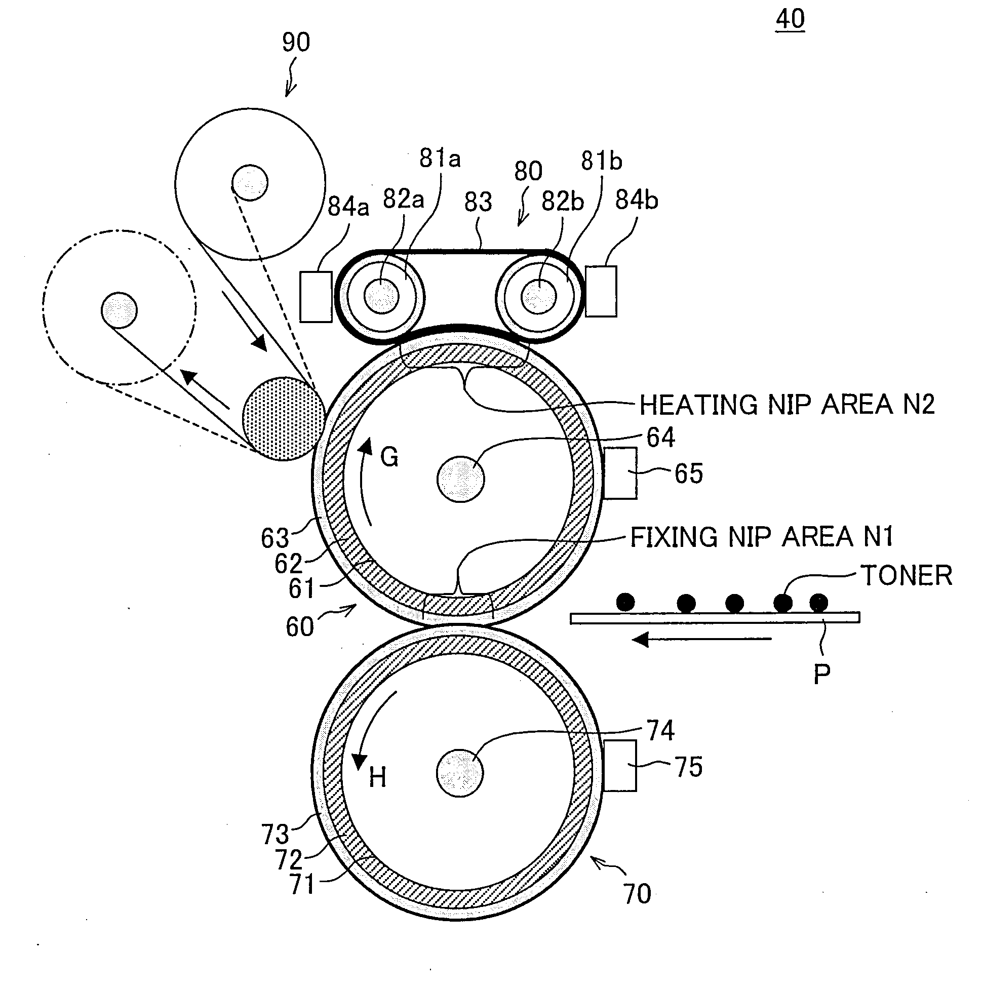
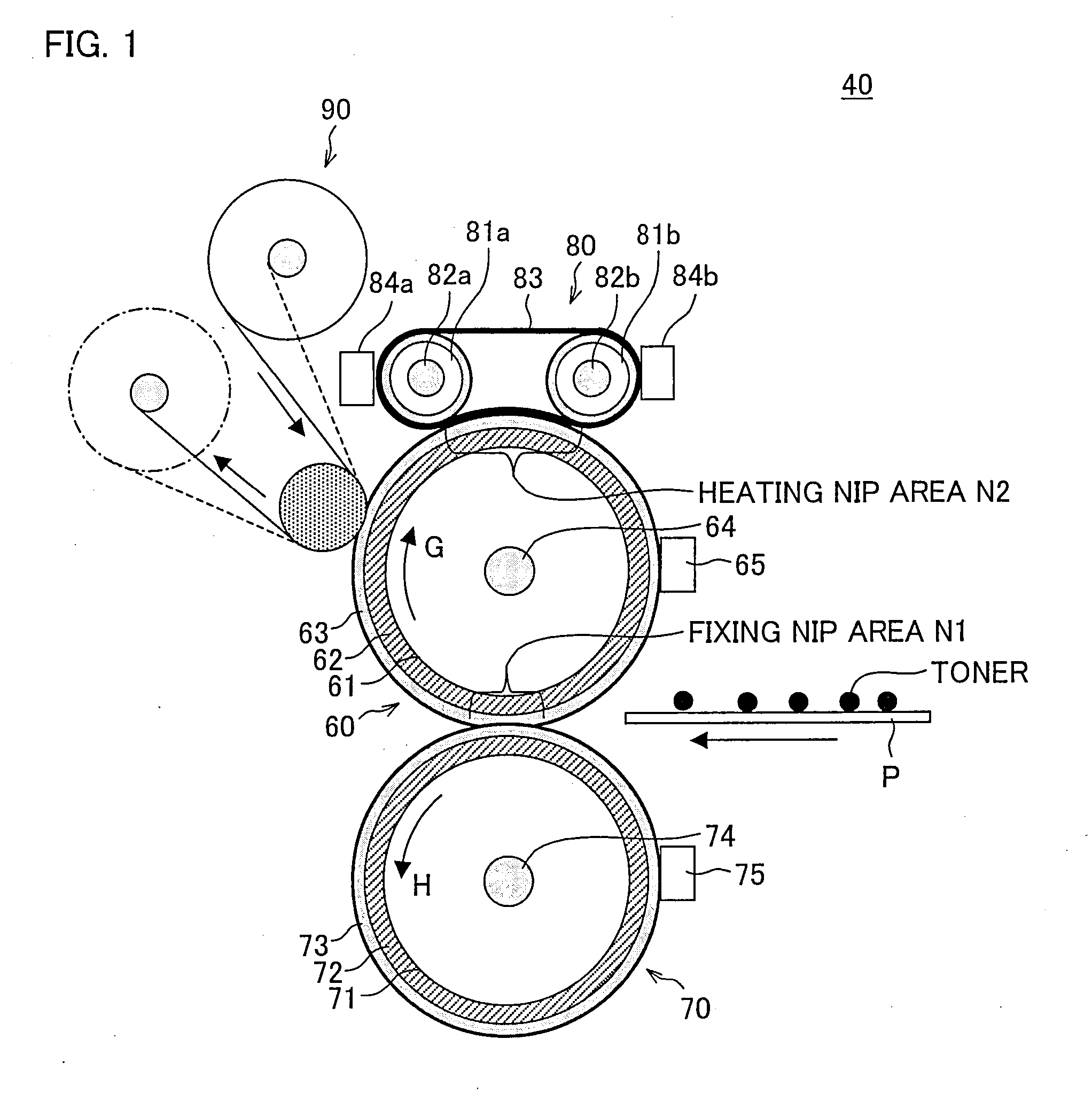
[0022]According to the above arrangement, by providing the heating roller for the pressure roller that faces the fixing roller, it is possible to reduce the warm-up time and to quickly and efficiently respond to decrease in temperature of the pressure roller during the fixing process. Note that since a temperature of the pressure roller may be lower than that of the fixing roller, the heating roller having a heat source therein can be used. This makes it possible to realize the fixing apparatus that is smaller in size than the fixing apparatus including the external heating device using the endless belt.
[0023]Further, quickly heating the pressure roller increases the amount of available heat supplied from the pressure roller to the recording material. As a result, the amount of heat to be supplied from the fixing roller is suppressed. This effect reduces temperature variations between the heating means, the support rollers, and the endless belt all of which are members for supplying heat to the surface of the fixing roller, thus suppressing rise in temperature of the endless belt that is in contact with the fixing roller. This makes it possible to suppress degradation due to temperatures of the surfaces of the endless belt and the fixing member, and to reduce unevenness of the image.

