6-Axis electromagnetically-actuated meso-scale nanopositioner

a nano-positioner and electromagnetic actuator technology, applied in the field of micro-fabricated nanopositioners, can solve the problems of thermal fluctuations that can generate relatively large position errors, require high-voltage power supplies, and cost thousands of dollars

Inactive Publication Date: 2007-09-27
MASSACHUSETTS INST OF TECH
View PDF22 Cites 23 Cited by
  • Summary
  • Abstract
  • Description
  • Claims
  • Application Information

AI Technical Summary

Benefits of technology

[0015] In one aspect of the invention, an electromagnetically actuated microfabricated nanopositioner includes a compliant mechanism and a plurality of microfabricated actuators. The compliant mechanism includes a stage, a support, a plurality of flexures coupled to the stage and to the support, and a plurality of beams each coupled to one of the flexures. The beams are sized and shaped so that their displacement generates a displacement of the stage relative to the support. The actuators are coupled to the beams, each actuator including a coil stack of first and second coils in the form of electrically conductive superposed layers extending parallel to the compliant mechanism. A magnet array is disposed in magnetic communication with the coil stack. The coils are each selectively, electrically actuatable to generate relative movement between the coil stack and the magnet array both in-plane and out-of-plane, so that the stage is configured for controlled movement with 6 degrees of freedom.

Problems solved by technology

Many of these devices operate under closed loop control, require high-voltage power supplies, and often cost thousands of dollars.
In addition, thermal fluctuations can generate relatively large position errors in macro-scale machines.
The mismatch between the length / time scales (i.e., range of motion and speed of movement) of macro-scale positioners and many nano-scale phenomena limits the use of these nanopositioners in future small-scale applications.
However, such small scale nanopositioners have not been previously developed.
Although much of the physics scale from macro- to micro-scale systems, microfabrication constraints fundamentally change the design methodology for small-scale nanopositioners.
Assembly and fabrication methods used to realize macro-scale electromagnetic (EM) actuators are generally unsuitable for building micro- and meso-scale (i.e., microfabricated) actuators.
Contrary to the conventional approaches used to fabricate macro-scale actuators, microfabricated micro-coil structures are limited to generally planar geometries.
A drawback, however, of this approach is that the coils are rigidly coupled to the movable stage, which results in a relatively large moving mass.
This large mass and its associated low resonance frequency, results in a relatively low bandwidth, i.e., slow response time.
This configuration also results in a relatively large footprint, which tends to undesirably limit component density.
In addition, the system as shown is limited to motion in 5 DOF (not 6), and suffers from a relatively complex fabrication process.

Method used


Image

  • 6-Axis electromagnetically-actuated meso-scale nanopositioner
  • 6-Axis electromagnetically-actuated meso-scale nanopositioner
  • 6-Axis electromagnetically-actuated meso-scale nanopositioner

Examples


Embodiment Construction

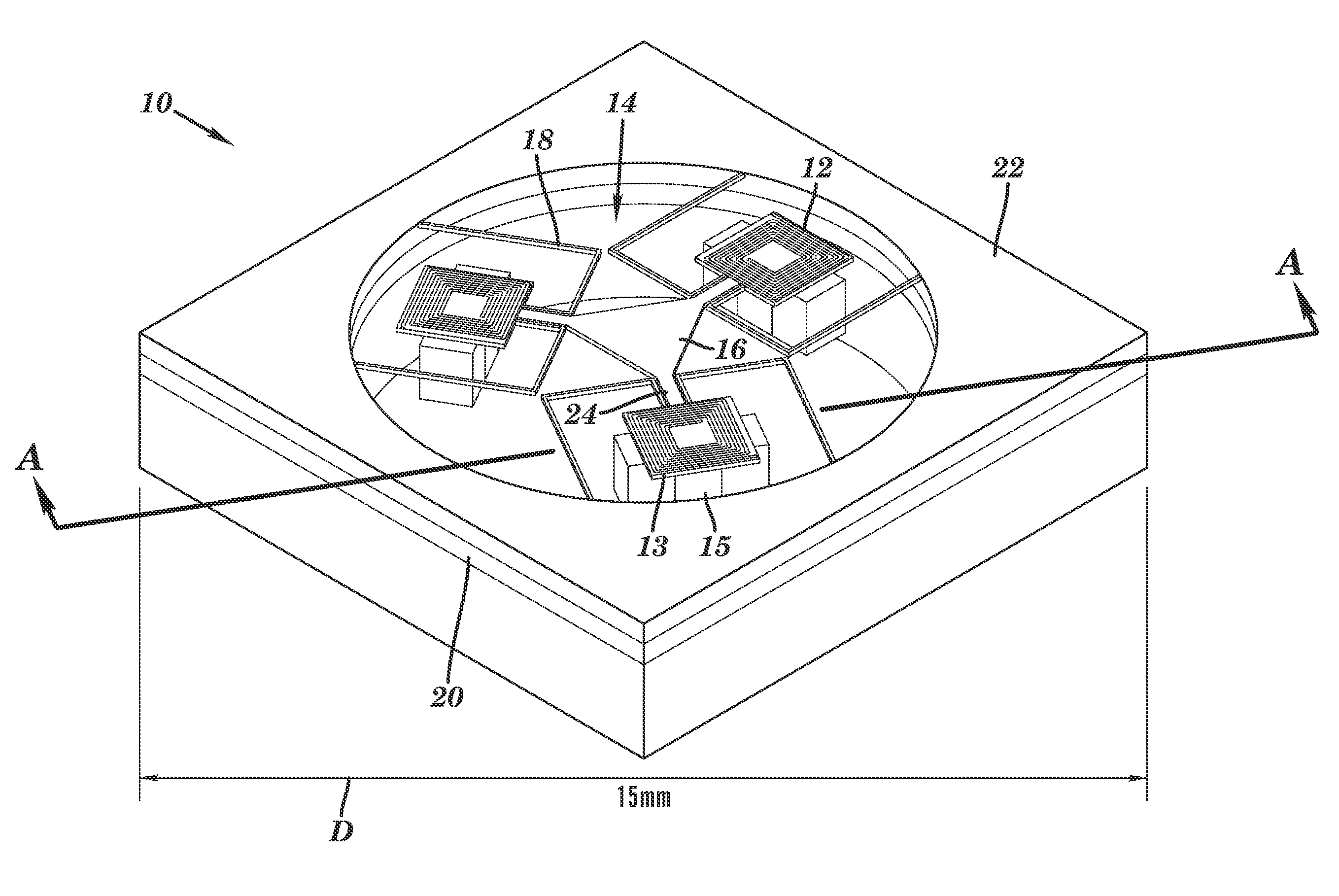
[0030] In the following detailed description, reference is made to the accompanying drawings that form a part hereof, and in which is shown by way of illustration, specific embodiments in which the invention may be practiced. These embodiments are described in sufficient detail to enable those skilled in the art to practice the invention, and it is to be understood that other embodiments may be utilized. It is also to be understood that structural, procedural and system changes may be made without departing from the spirit and scope of the present invention. The following detailed description is, therefore, not to be taken in a limiting sense, and the scope of the present invention is defined by the appended claims and their equivalents. For clarity of exposition, like features shown in the accompanying drawings are indicated with like reference numerals and similar features as shown in alternate embodiments in the drawings are indicated with similar reference numerals.

[0031] As sh...


PUM


Abstract

A MEMS actuator includes a coil stack in the form of microfabricated, electrically conductive first and second superposed layers. A magnet array is superposed in magnetic communication with the coil stack, with first and second coils being selectively, electrically actuatable to generate relative movement between the coil stack and the magnet array both in-plane and out-of-plane. In various embodiments, a plurality of the actuators are integrally coupled to a microfabricated compliant mechanism to provide a high bandwidth, six degree of freedom nanopositioner.

Description

RELATED APPLICATION [0001] This application claims the benefit of U.S. Provisional Application Ser. No. 60 / 777,252, entitled 6-Axis Electromagnetically-Actuated Meso-Scale Nanopositioner, filed on Feb. 27, 2006, the contents of which are incorporated herein by reference in their entirety for all purposes. This application is a Continuation-In-Part of U.S. patent application Ser. No. 11 / 037,866, filed on Jan. 18, 2005, entitled Multiple Degree of Freedom Micro Electro-Mechanical System Positioner and Actuator. This application is also related to U.S. Pat. No. 7,093,827, filed on Jun. 19, 2002, entitled Multiple Degree Of Freedom Compliant Mechanism, the contents of which are incorporated herein by reference in their entirety for all purposes.BACKGROUND [0002] 1. Technical Field [0003] This invention relates to MEMS devices, and more particularly to a microfabricated nanopositioner capable of movement in six degrees of freedom. [0004] 2. Background Information [0005] Throughout this a...

Claims


Application Information

Patent Timeline
Patent Type & Authority Applications(United States)
IPC IPC(8): B81B7/02
CPCB81B3/0062B81B2201/038B81B2203/0109Y10T74/20348B81B2203/055B81B2203/058B81B2203/053
Inventor CULPEPPER, MARTIN L.GOLDA, DARIUSZ
Owner MASSACHUSETTS INST OF TECH
Why Eureka
Try Eureka