Radar device and MEMS mirror device therefor

a technology of a radar device and a mirror device, applied in the field of radar, can solve the problems of not being able to detect inputs with low brightness, limit the detection of reflected light, etc., and achieve the effect of accurately and simultaneously observed high brightness

Inactive Publication Date: 2007-09-27
ORMON CORP
View PDF1 Cites 45 Cited by
  • Summary
  • Abstract
  • Description
  • Claims
  • Application Information

AI Technical Summary

Benefits of technology

[0027] In summary, the present invention makes it possible for the light-reflecting mirror itself to observe the quantity of light reflected thereby. Moreover, since output signals ...

Problems solved by technology

Since PIN photodiodes have a low S/N ratio and the sensitivity cannot be made high, there was a limit to the detection of reflected light with low brightness being returned from a distan...

Method used


Image

  • Radar device and MEMS mirror device therefor
  • Radar device and MEMS mirror device therefor
  • Radar device and MEMS mirror device therefor

Examples


Embodiment Construction

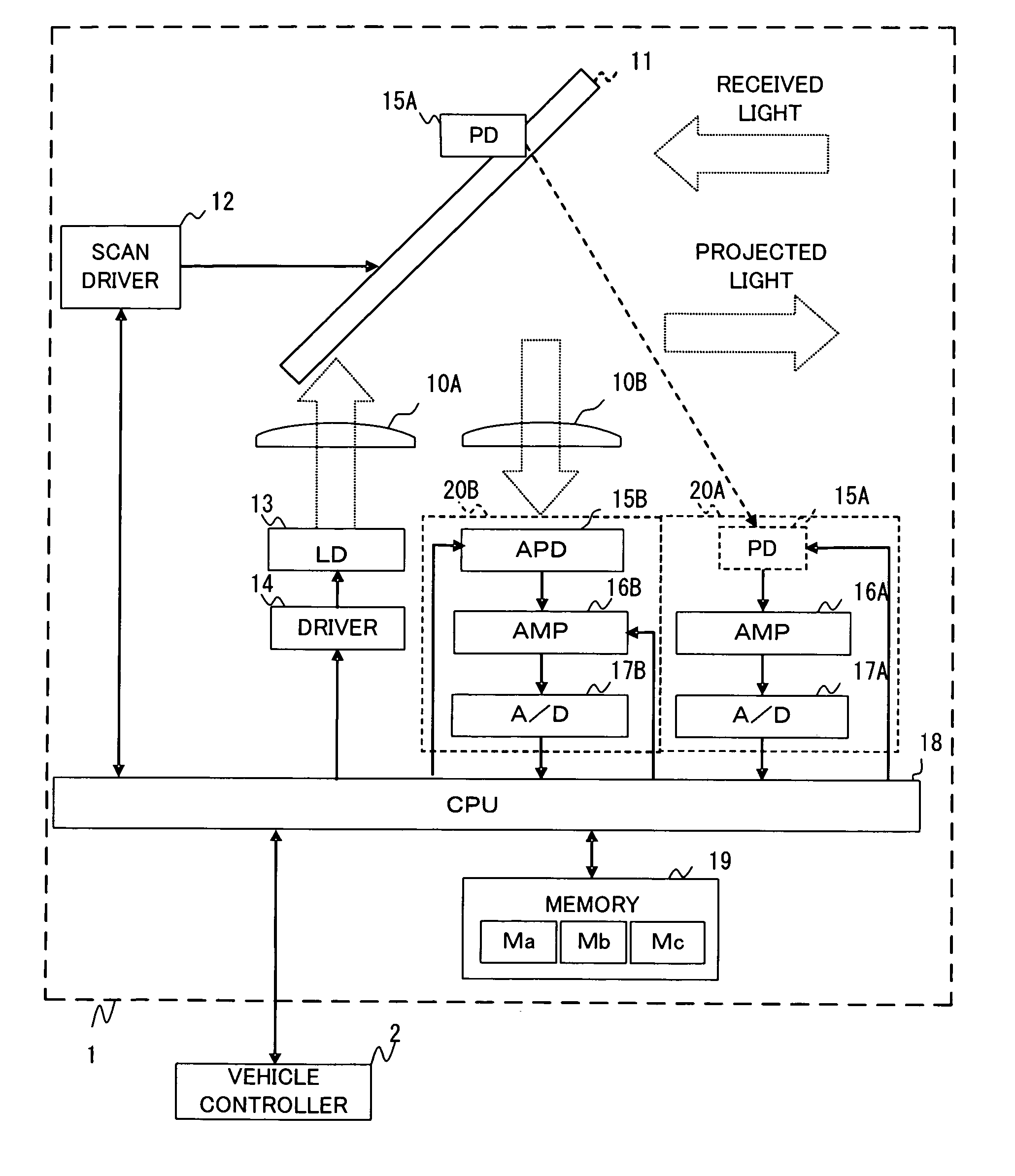
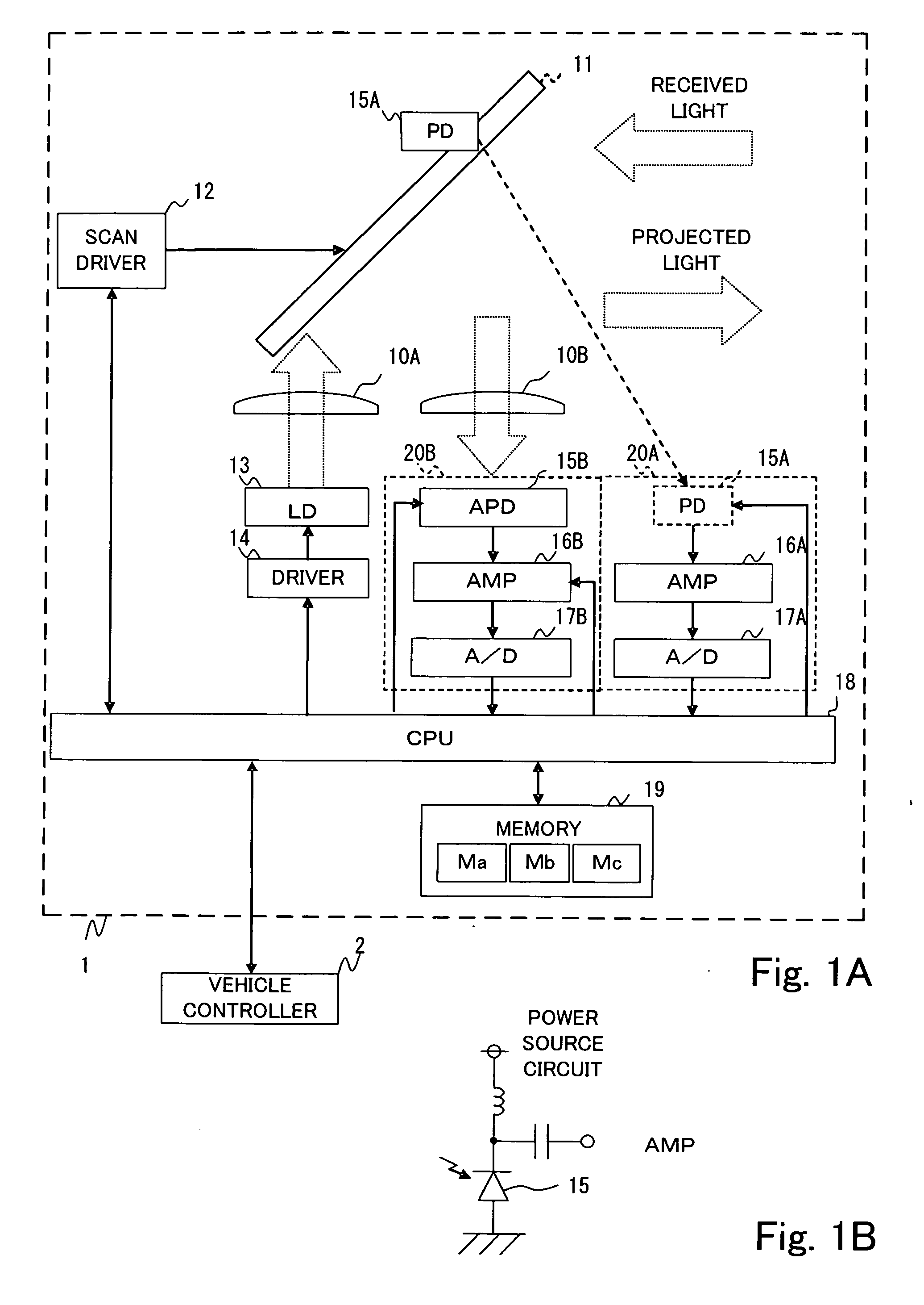
[0035]FIG. 1A is a block diagram for showing the structure of a radar device 1 of this invention, provided with a light projecting lens 10A, a light receiving lens 10B, a reflective mirror 11, a scan driver 12, a laser diode (LD) 13, a driver 14, (first and second) light receiving circuits 20A and 20B, a CPU 18 and a memory 19.

[0036] The light projecting and receiving lenses 10A and 10B are affixed to a same frame such that their optical axes are parallel to each other. The laser diode 13 is set at the focal point of the light projecting lens 10A, and an APD 15B is set at the focal point of the light receiving lens 10B.

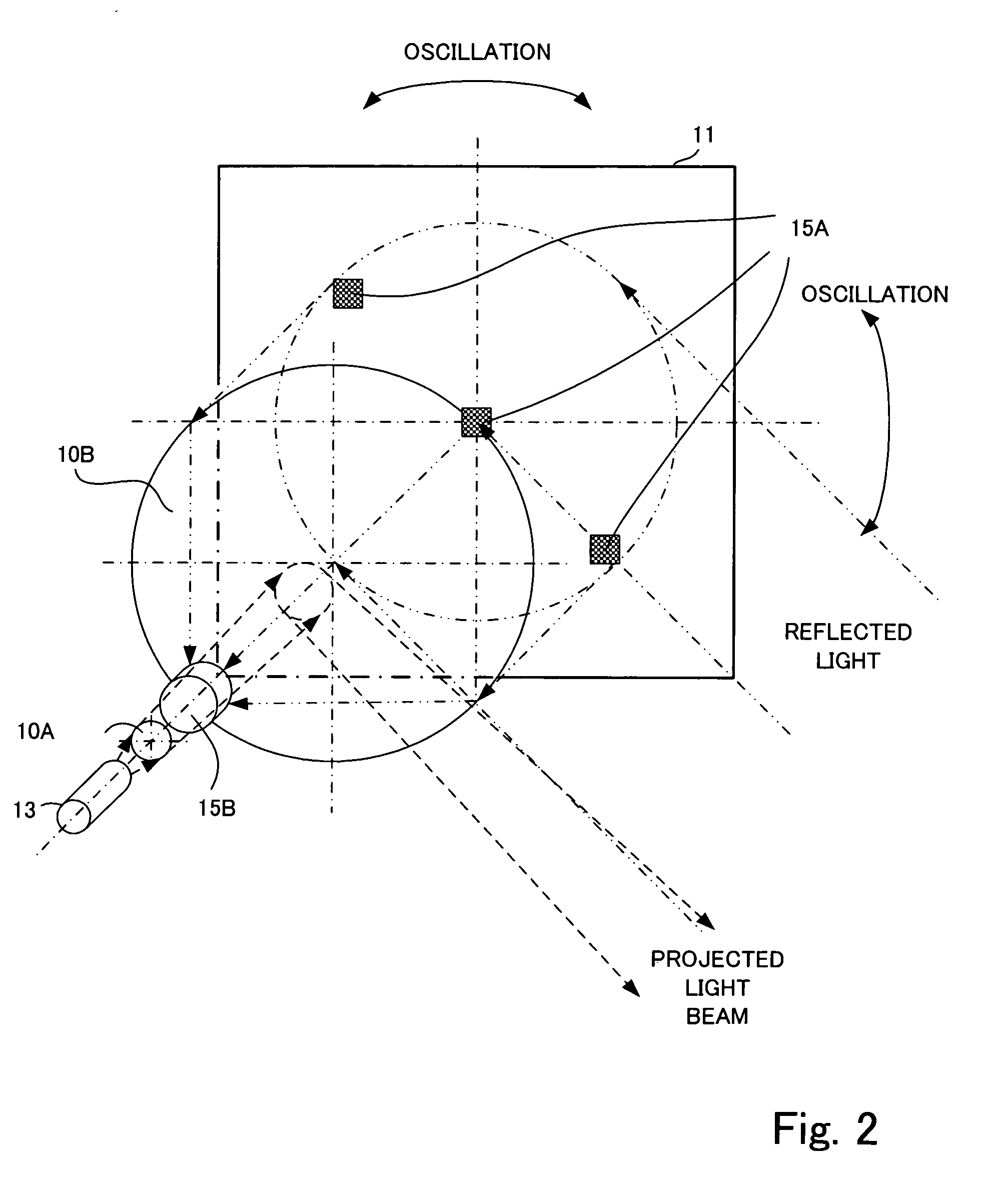
[0037] The laser diode 13 is driven by the driver 14. The driver drives the laser diode 13 according to outputs from the CPU 18. The laser light from the laser diode 13 is projected in the form of a beam (as shown in FIG. 2) by means of the light projecting lens 10A. This infrared beam of light is reflected by the reflective mirror 11 and projected outward. As this ...


PUM


Abstract

A radar device includes a light projecting part that generates laser light, a light projecting lens that converges the generated laser light to form a beam, a reflective mirror for reflecting the converged beam to project it in a specified search direction and for reflecting returning light from this search direction, a light receiving lens for converging the returning light reflected by the reflective mirror, and a scanning part for moving the beam in a scanning manner. There are two light receiving parts which are different in photosensitivity, and a synthesizing part outputs a synthesized signal formed by synthesizing output signals from these two light receiving parts.

Description

[0001] This application claims priority on Japanese Patent Applications 2006-071209 filed Mar. 15, 2006 and 2006-313087 filed Nov. 20, 2006. BACKGROUND OF THE INVENTION [0002] This invention relates to a radar device for projecting a near-infrared laser beam forward and measuring the distance to an object by observing its reflected light, as well as an MSMS mirror device that is appropriate therefor. [0003] Radar devices for projecting a near-infrared laser beam forward to monitor the presence of objects such as a front going vehicle, pedestrians and obstacles and to measure their distances and directions by observing its reflected light are coming to be used popularly in recent years. Conventionally, a PIN-type photodiode was commonly used as the light receiving element for receiving the reflected light. Since PIN photodiodes have a low S / N ratio and the sensitivity cannot be made high, there was a limit to the detection of reflected light with low brightness being returned from a ...

Claims


Application Information

Patent Timeline
IPC IPC(8): H01Q3/00
CPCG01S7/4811G01S17/42G01S7/4817
Inventor ISHIO, WATARUFUJIOKA, RYOJI
Owner ORMON CORP
Why Eureka
Try Eureka