Image recording method and image recording apparatus
a recording method and image technology, applied in the direction of duplicating/marking methods, material nanotechnology, inks, etc., can solve the problems of low image quality, affecting the speed of high-speed printing, and affecting the quality of high-speed printing, so as to prevent ink bleeding, reduce pile height, and reduce the effect of pile heigh
- Summary
- Abstract
- Description
- Claims
- Application Information
AI Technical Summary
Benefits of technology
Problems solved by technology
Method used
Image
Examples
working examples
[0217]Next, the present invention is described in detail by means of working examples, but the present invention is not limited to these examples. In the following description, the symbol “%” refers to the “weight percentage”, unless stated otherwise.
working example 1
1-1 Preparation of Yellow Ink Y-1
[0218]1.0 parts of C.I. Solvent Yellow 14 were mixed with 99.0 parts of acetone and agitated while heating at 40° C., to achieve a uniform solution. This mixed solution was then added to and mixed with a solution formed by dissolving 1.0 parts of the below-described polymer dispersant BP-1 having an average molecular weight of 35000, in 99.0 parts of tetrahydrofuran. Thereupon, 10.0 parts of water were added. Subsequently, the acetone and the tetrahydrofuran were removed completely in a rotary evaporator, to yield a coloring material dispersion of C.I. Solvent Yellow 14.
[0219]400 g of the coloring material dispersion of C.I. Solvent Yellow 14, 150 g of tripropylene glycol, 50 g of triethylene glycol, 50 g of 1% tris-hydroxyaminomethane-hydrochloric acid buffer, and 10 g of Olefin E1010 manufactured by Nisshin Kagaku Kogyo, were mixed into 340 g of deionized water and agitated, to yield yellow ink Y-1. The volume-average particle size of the coloring ...
working example 2
2-1 Preparation of Magenta Ink M-1
[0222]A magenta ink M-1 was obtained by exactly the same method as above, except that the C.I. Solvent Yellow 14 was substituted with C.I. Solvent Red 27. The volume-average particle size of the coloring material in the ink thus obtained was 45 nm.
2-2 Evaluation of Image Quality
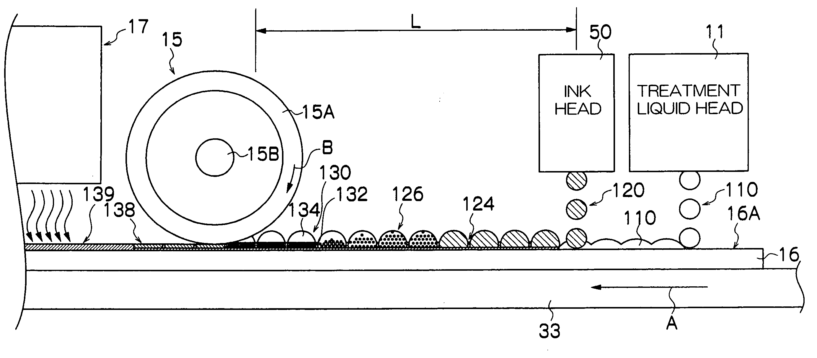
[0223]Table 2 shows the results of an image quality evaluation using the same method as working example 1. Similarly to the results according to working example 1, it can be seen that the pile height is reduced when droplets are ejected at the liquid droplet size according to the present invention.
TABLE 2Liquid dropletsizeBleeding *1Pile height *2Comments4 pl100poorComparative Example3 pl101averageComparative Example2.5 pl 100goodPractical Example2 pl100goodPractical Example1.5 pl 98goodPractical Example
PUM
| Property | Measurement | Unit |
|---|---|---|
| Volume | aaaaa | aaaaa |
| Volume | aaaaa | aaaaa |
| Volume | aaaaa | aaaaa |
Abstract
Description
Claims
Application Information
 - R&D
- Intellectual Property
- Life Sciences
- Materials
- Tech Scout
- Unparalleled Data Quality
- Higher Quality Content
- 60% Fewer Hallucinations
Browse by: Latest US Patents, China's latest patents, Technical Efficacy Thesaurus, Application Domain, Technology Topic, Popular Technical Reports.
© 2025 PatSnap. All rights reserved.Legal|Privacy policy|Modern Slavery Act Transparency Statement|Sitemap|About US| Contact US: help@patsnap.com


