Printing apparatus and printing method

Active Publication Date: 2019-05-23
MIMAKI ENG
View PDF9 Cites 0 Cited by
  • Summary
  • Abstract
  • Description
  • Claims
  • Application Information

AI Technical Summary

Benefits of technology

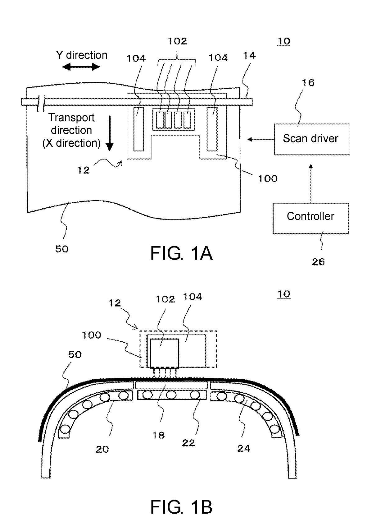
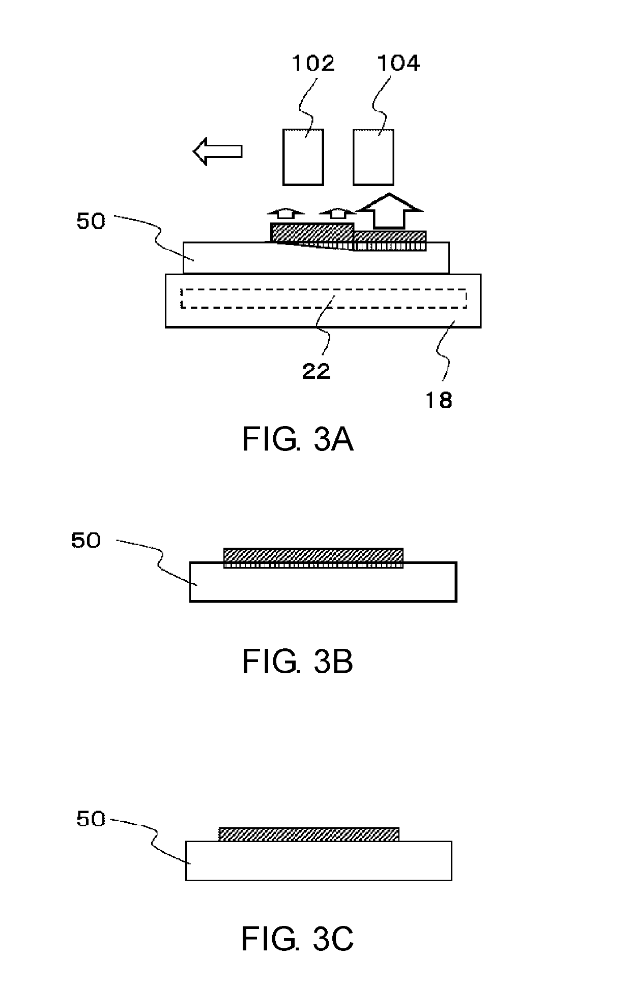
[0019]In this configuration, the printing apparatus may perform multi-pass printing. The number of print passes in this instance may be less than or equal to eight. For higher printing speeds, it is preferable that the number of print passes is set to less than eight (for example, less than or equal to four passes). According to this configuration, higher printing speeds may be feasible in multi-pass printing, with a suitably reduced number of print passes. While the amount of ink landing on the medium per unit area and per unit time may increase with a smaller number of print passes, the ink may be favorably prevented from bleeding by volatilizing the solvent away from the ink under ultraviolet irradiation.
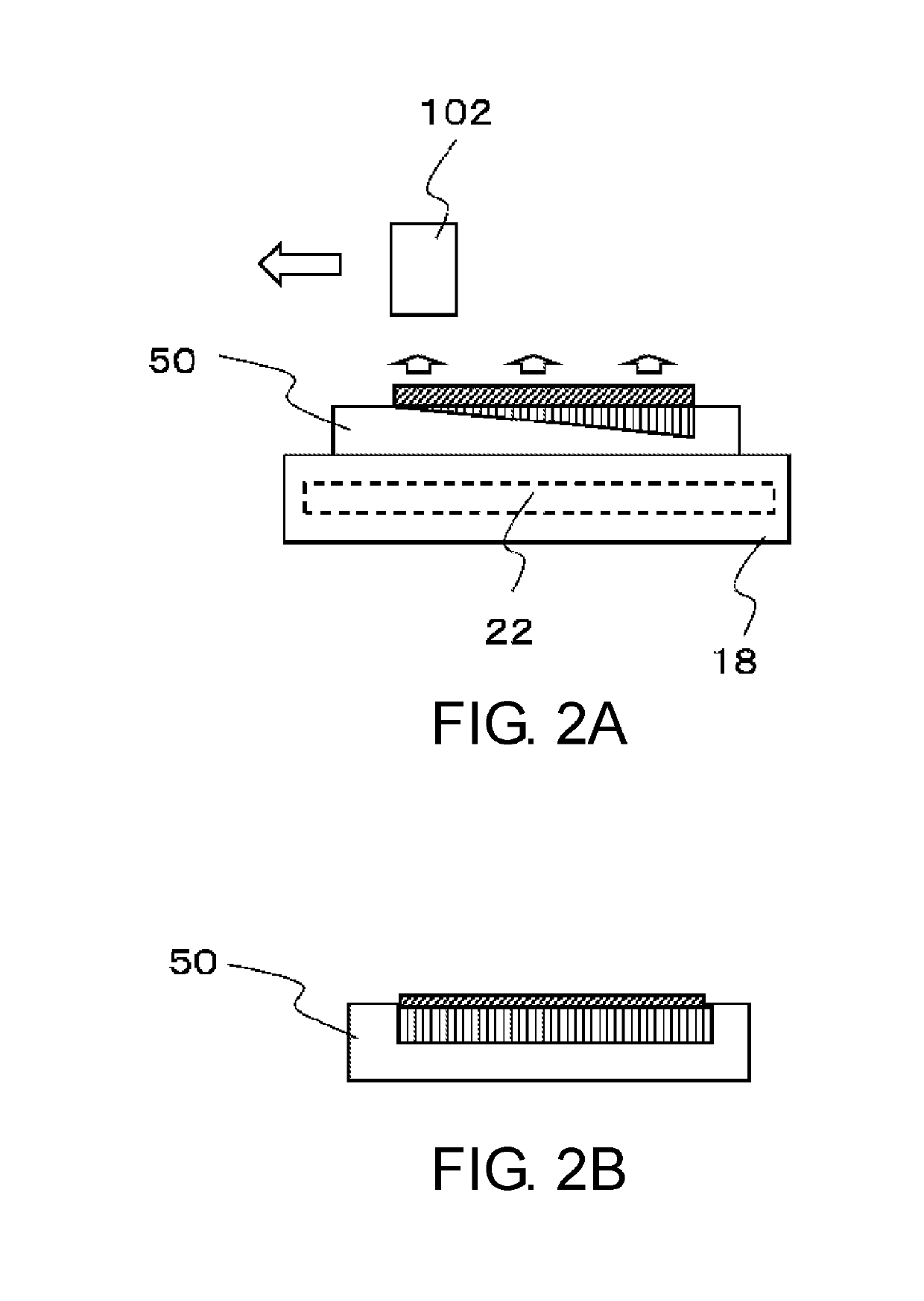
[0020]The scope of this disclosure may include a printing method technically characterized as with the printing apparatus described so far. This disclosure may provide a printing method for performing inkjet printing using a medium, the printing method including steps of: (1) ejecting ink to the medium from an inkjet head and adhering the ink to the medium, the ink containing a colorant, an ultraviolet absorbent, a resin, and an aqueous solvent that emulsifies or suspends the resin; and (2) irradiating the ink adhered to the medium with ultraviolet light using an ultraviolet light source to heat the ink to a temperature lower than a boiling point of the ink and high enough to pr

Problems solved by technology

If this means is employed, however, particular print mediums having such an ink receiving layer previously formed thereon can only be used for printing.
Further, the ink solvent may remain in the ink receiving layer, which may lead to other issues.
When a medium is used that needs to be rolled up after the printing, for example, ink may be likely to bleed through to the back surface of the medium being collected by a take-up device.
In case paper is used as the underlayer of the ink receiving layer, abundant ink consumption, as in color image printing, may increase the likelihood of curling, cockling or the like of a medium used.
Such pretreatment should be handled by a professional specialist, resulting in time loss and cost increase.
At higher heating temperatures, however, some problems may occur.
For example, ink may boil and generate bubbles, causing the ink surface to become uneven, and the

Method used


Image

  • Printing apparatus and printing method
  • Printing apparatus and printing method
  • Printing apparatus and printing method

Examples


working examples

Example 1

[0229]Tables 1 and 2 show compositions of ultraviolet absorbent-containing inks. The materials shown in these tables were mixed and stirred with a stirrer for approximately three hours to prepare a cyan ink and a magenta ink.

TABLE 1IngredientsWt. %Composition ofPigment-dispersed liquid, cyan12cyan inkResin20Diethylene glycol monobutyl ether201,2-butanediol30Surfactant0.5Ultraviolet absorbent1WaterRemainder

TABLE 2IngredientsWt. %Composition ofPigment-dispersed liquid, magenta18magenta inkResin20Diethylene glycol monobutyl ether201,2-butanediol30Surfactant0.5Ultraviolet absorbent1WaterRemainder

The pigment dispersing liquids for the cyan ink and the magenta ink shown in Tables 1 and 2 were respectively FUJI SP BLUE 6559 (Fuji Pigment Co., Ltd.) and FUJI SP MAGENTA 9430 (Fuji Pigment Co., Ltd.). The resin used for both of the inks was SUPERFLEX 126 (DKS Co., Ltd.). The surfactant used for both of the inks was BYK-349, silicon-based surfactant (BYK Japan KK). The ultraviolet abs...

example 2 verification

of Heat Generation by Ultraviolet Irradiation (Test 1)

[0231]The cyan ink prepared in the example 1 was collected in the amount of 10 g and put on a laboratory dish, and then irradiated for one minute with ultraviolet light radiated from an ultraviolet LED lamp. The ultraviolet light had the luminous intensity of 1150 mW / cm2 and the wavelength of 385 nm. A thermograph was used to measure temperatures on the ink surface, and a highest temperature reachable on the ink surface was recorded.

[0232]The cyan ink prepared in the comparative example 1 was tested in the same manner. Table 3 shows the obtained result.

example 3

Measurement of Surface Properties and Ink Bleeding Width of Printed Matter (Test 2)

[0233]By using a printer (CJV-150, MIMAKI ENGINEERING CO., LTD.) filled with the cyan ink and the magenta ink prepared in the example 1, inkjet printing was performed, in which the inks were ejected so as to land next to each other on a medium made of polyvinyl chloride (PWS-G, MIMAKI ENGINEERING CO., LTD.) at the concentration of 100%. The inks were then irradiated with ultraviolet light and dried with a pre-heater, a printing heater, and an after-heater set to a platen temperature 55° C. Ultraviolet LED lamps were attached to both sides of the inkjet heads of the printer and set to start to radiate ultraviolet light having the luminous intensity of 1150 mW / cm2 and the wavelength of 385 nm in approximately 0.7 seconds after the inks were ejected to the polyvinyl chloride medium from the inkjet heads and cease to radiate ultraviolet light approximately 0.1 seconds later. The surface properties of the ...


PUM

PropertyMeasurementUnit
Temperatureaaaaaaaaaa
Fractionaaaaaaaaaa
Fractionaaaaaaaaaa

Abstract

A printing apparatus is provided that effectively prevents the risk of ink bleeding so as to obtain a high-quality print result. The printing apparatus includes an inkjet head that ejects droplets of ink using inkjet technique so as to adhere the ink to the medium, and an ultraviolet light source that radiates ultraviolet light. The ink contains a colorant, an ultraviolet absorbent, a resin, and an aqueous solvent that emulsifies or suspends the resin. The ultraviolet light source irradiates the ink adhered to the medium with ultraviolet light to heat the ink to a temperature lower than a boiling point of the ink and high enough to prevent the ink from bleeding, so that the aqueous solvent is at least in part volatilized and removed from the ink.

Description

CROSS REFERENCE TO RELATED APPLICATIONS[0001]This application claims the priority benefit of Japanese Patent Application No. 2017-221608, filed on Nov. 17, 2017. The entirety of the above-mentioned patent application is hereby incorporated by reference herein and made a part of this specification.TECHNICAL FIELD[0002]This disclosure relates to a printing apparatus and a printing method.DESCRIPTION OF THE BACKGROUND ART[0003]Conventionally, inkjet printers that perform inkjet printing are used for various purposes (for example, see Internet URL http: / / www.mimaki.co.jp). Inks often used in the inkjet printers may include evaporation-drying inks, for example, aqueous inks including aqueous pigment inks, latex inks, and inks in which pigment-encapsulated resin particles are dispersed, and organic solvent-containing solvent inks. The evaporation-drying ink refers to ink dried and fixable to a print medium by evaporating a solvent included in the ink. In the latex ink, among the mentioned...

Claims


Application Information

Patent Timeline
IPC IPC(8): B41M5/00B41J11/00B41J2/21
CPCB41M5/0023B41J11/002B41J2/211B41M7/0081B41M7/009C09D11/10C09D11/32C09D11/38D06P5/30D06P5/2005D06P1/44D06P1/6426D06P1/65112D06P1/65125D06P1/673B41J11/00214
Inventor SHINOHARA, MASANOBUNAMIKI, TAKASHI
Owner MIMAKI ENG
Why Eureka
Try Eureka