Objective lens, optical pickup, and optical information processing apparatus using the same

a technology of optical information processing apparatus and objective lens, which is applied in the field of optical information professing, can solve the problems of increasing the weight of the construction that uses two lenses, the numerical aperture value change between the optical recording media of different specifications, and the construction is contradictory to the requirement of downsizing and cost reduction

Inactive Publication Date: 2007-09-27
RICOH KK
View PDF17 Cites 5 Cited by
  • Summary
  • Abstract
  • Description
  • Claims
  • Application Information

AI Technical Summary

Benefits of technology

[0032] Another and more specific object of the present invention is to achieve a two-generation compatibility between optical recording technology of different generations such as the blue optical recording and the DVD, without providing an aperture switching element and is simultaneously capable of simplifying the assembling process and achieving weight reduction of the actuator or reduction of the number of parts of the actuator.
[0156] Thus, it becomes possible to eliminate a dedicated element for aperture switching and the weight of the actuator is reduced. Thereby, the number of steps for assembling the actuator is reduced.

Problems solved by technology

While such compatibility between different specifications can be achieved by providing a conventional optical pickup in addition to the optical pickup designed according to the new specification, such a construction is contradictory to the requirement of downsizing and cost reduction.
However, the use of such a compound lens raises the problems in that it requires a bonding process at the time of manufacturing of the objective lens and there arises the problem of increase of weight associated with the construction that uses two lenses.
Such a problem was also noticed in the DVD / CD compatible optical pickup.
In addition to the foregoing problem of aberration, there arises another problem in that the numerical aperture value changes between the optical recording media of different specifications.
Further, according to the method described in the foregoing ISOM Abstract, op. cit., no satisfactory wave front performance is obtained when to achieve the compatibility between the DVD optical recording medium and the CD optical recording medium.
In the case of an optical pickup, on the other hand, there exist various factors that may become the cause of the error such as the thickness error of the optical recording medium, the tilt error of the optical recording medium, the defocus error caused by displacement between the optical recording medium and the objective lens.
Because of this, it was inevitable to make the design to target the intermediate point of phase compensation condition when to minimize the aberration in both of DVD and CD, while such an approach could not reduce the aberration sufficiently.
Particularly, the numerical aperture switching element designed for three-generation optical recording and playback so as to operate in three steps has a complex structure, and design and manufacture thereof becomes difficult.
Further, in spit of its complex construction, such a three-step numerical aperture switching element cannot provide sufficient compensation with regard to the wavefront characteristics and transmission characteristics.

Method used


Image

  • Objective lens, optical pickup, and optical information processing apparatus using the same
  • Objective lens, optical pickup, and optical information processing apparatus using the same
  • Objective lens, optical pickup, and optical information processing apparatus using the same

Examples


first embodiment

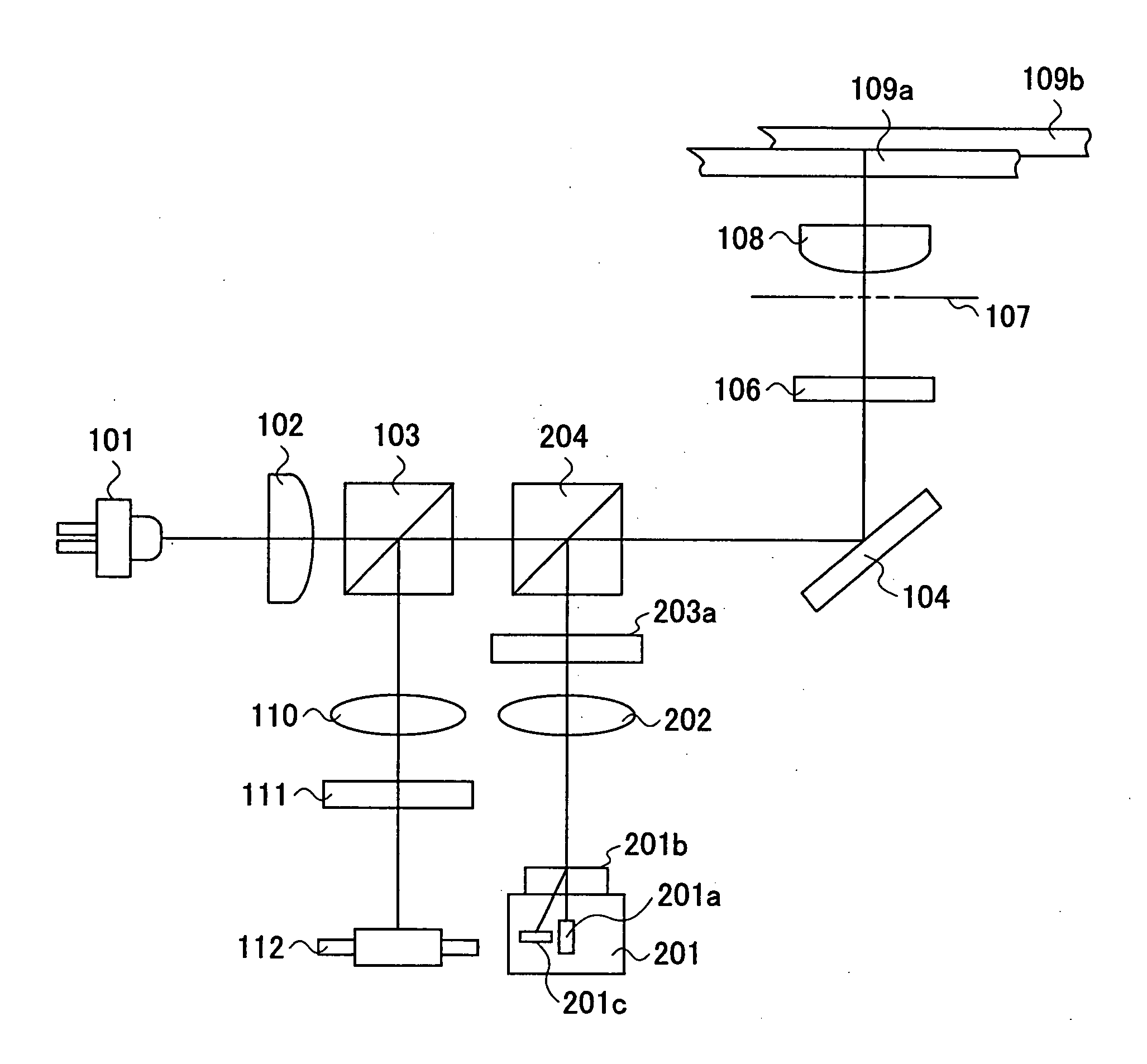
[0213]FIG. 7 is a diagram showing the schematic construction of an optical pickup according to a first embodiment of the present invention capable of carrying out any of recording, playback and erasing of information to and from any of: a blue optical recording medium having a substrate thickness of 0.6 mm at the side where an optical irradiation is made and designed for use with an optical source having a wavelength of 407 nm and an optical system having a numerical aperture value NA of 0.67; and a DVD optical recording medium having a substrate thickness of 0.6 mm at the side where an optical irradiation is made and designed for use with an optical source having a wavelength of 660 nm and an optical system having a numerical aperture value NA of 0.65.

[0214] While the technology of the blue generation optical recording technology addressed in the first embodiment of the present invention is still in the process of consolidation, the present embodiment will be explained for an exem...

example 1

[0243] Next, an optical pickup equipped with a phase compensation element that uses optical diffraction for the compensation element of the spherical aberration will be explained with reference to FIG. 7 as Example 1 of the present invention.

[0244] In the case an optical spot is formed on a DVD recording medium 109 by using an optical beam having a wavelength of 660 nm together with the single objective lens 108, which is optimized such that the wavefront aberration becomes minimum for the optical beam having the wavelength of 407 nm, by supplying the foregoing optical beam of the 660 nm wavelength to the objective lens 108 via an infinite optical system, there arises a spherical aberration shown in FIG. 12B due to the difference in the wavelength. It should be noted that FIG. 12B shows the wavefront aberration at the wavelength of 407 nm.

[0245] Thus, in Example 1, the optical pickup uses a finite optical system for DVD and further provides the phase compensation element 203a in s...

example 2

[0265]FIG. 15 is a diagram showing the schematic construction of the optical pickup according to Example 2 of the present invention.

[0266] Referring to FIG. 15, Example 2 shows an optical pickup capable of carrying out recording, playback and erasing of information to and from any of the blue optical recording medium by using the wavelength band of 407 nm, numerical aperture value NA of 0.67 and the substrate thickness of 0.6 mm at the side to which the optical irradiation is made and the red optical recording medium by using the wavelength band of 660 nm, numerical aperture value NA of 0.65 and the thickness of 0.6 mm at the side to which the optical irradiation is made.

[0267] The difference of the optical pickup of FIG. 15 over the optical pickup of FIG. 7 is in the point that a phase compensation element of stepped shape shown in FIG. 16 is used in place of the phase compensation element 203a having a blazed pitch pattern shown in FIG. 14B. Associated with this, the present exa...


PUM

PropertyMeasurementUnit
wavelengthaaaaaaaaaa
wavelength rangeaaaaaaaaaa

Abstract

An optical pickup includes a first optical source producing a first optical beam having a wavelength λ1, a second optical source producing a second optical beam having a wavelength λ2 (λ1<2), and a single objective lens focusing any of the first and second optical beams to an optical recording medium, the first optical beam is incident to the objective lens as a parallel beam and the second optical beam is incident to the objective lens as a divergent optical, wherein an aperture is provided at a front side of the objective lens with offset from a principal point at the front side by a distance t given by an equationt=L−NA1·f / tan(asin(NA2obj)),wherein f represents a focal distance of the objective lens, NA1 represents the numerical aperture at the side of the image surface when the first optical source is turned on, NA2obj represents the numerical aperture at the front side when the second optical source is turned on, and L represents the object distance at the time when the second optical source is turned on.

Description

BACKGROUND OF THE INVENTION [0001] The present invention generally relates to optical information professing and more particularly to an objective lens and an optical pickup for conducting at least one of information recording, information playback and erasing of information to optical media designed for blue wavelength band, red wavelength band or infrared wavelength band, as well as the information processing apparatus that uses the same. [0002] For the means for saving video information, audio information or data in a computer, the use of optical recording media such as a CD having a recording capacity of 0.65 GB, or a DVD having a recording capacity of 4.7 GB, is spreading. In these days, there is an acute demand for further improvement of recording density for more recording capacity. [0003] In order to increase the recording density in such an optical recoding medium, it is necessary to increase the numerical aperture (NA) value of the objective lens or reduce the wavelength o...

Claims


Application Information

Patent Timeline
Patent Type & Authority Applications(United States)
IPC IPC(8): G11B7/135G11B7/00G11B7/125
CPCG11B7/1275G11B7/1353G11B7/1367G11B2007/0006G11B7/139G11B7/13922G11B7/13925G11B7/1374
Inventor HIRAI, HIDEAKI
Owner RICOH KK
Why Eureka
Try Eureka