Wireless communication apparatus

a communication apparatus and wireless technology, applied in the field of wireless communication apparatuses, can solve the problems of inability to achieve satisfactory frequency use efficiency, difficult for a transceiver to adopt the uwb communication system, and failure to perform communication as a system

Inactive Publication Date: 2007-09-27
SONY CORP
View PDF8 Cites 37 Cited by
  • Summary
  • Abstract
  • Description
  • Claims
  • Application Information

AI Technical Summary

Benefits of technology

[0041]It is desirable to provide an excellent MB-OFDM wireless communication apparatus that is ca...

Problems solved by technology

However, since a signal output from an existing communication system is a narrow-band signal, only part of the band used by the UWB communication system has an influence, if the UWB emission level is reduced to the specified level or less throughout the band by detecting the signal output from the different system, satisfactory frequency use efficiency is not achieved.
However, it is difficult for a transceiver adopting the UWB communication system corresponding to the known FCC wireless equipment rule to have the DAA function.
In a DSSS-UWB transceiver, when the presence of a different narrow-band wireless system in a used frequency band is detected, if, in order to avoid interference, a notch is provided only in a band region in which the different narrow-band wireless system is detected, a transmission waveform is distorted, resulting in failure to perform communication as a system.
However, in order to actually reduce the noise floor level of an antenna terminal to −70 dBM/MHz or less, a problem in a radio frequency (RF) circuit module is more crucial.
Thus, a desired characteristic is not achieved.
However, inserting the HPF prevents a baseband unit of the receiver from obtaining information on a frequency in the vicinity of the local frequency of the receiver.
However, in the actual IC, due to asymmetry caused by relative varia...

Method used


Image

  • Wireless communication apparatus
  • Wireless communication apparatus
  • Wireless communication apparatus

Examples


Embodiment Construction

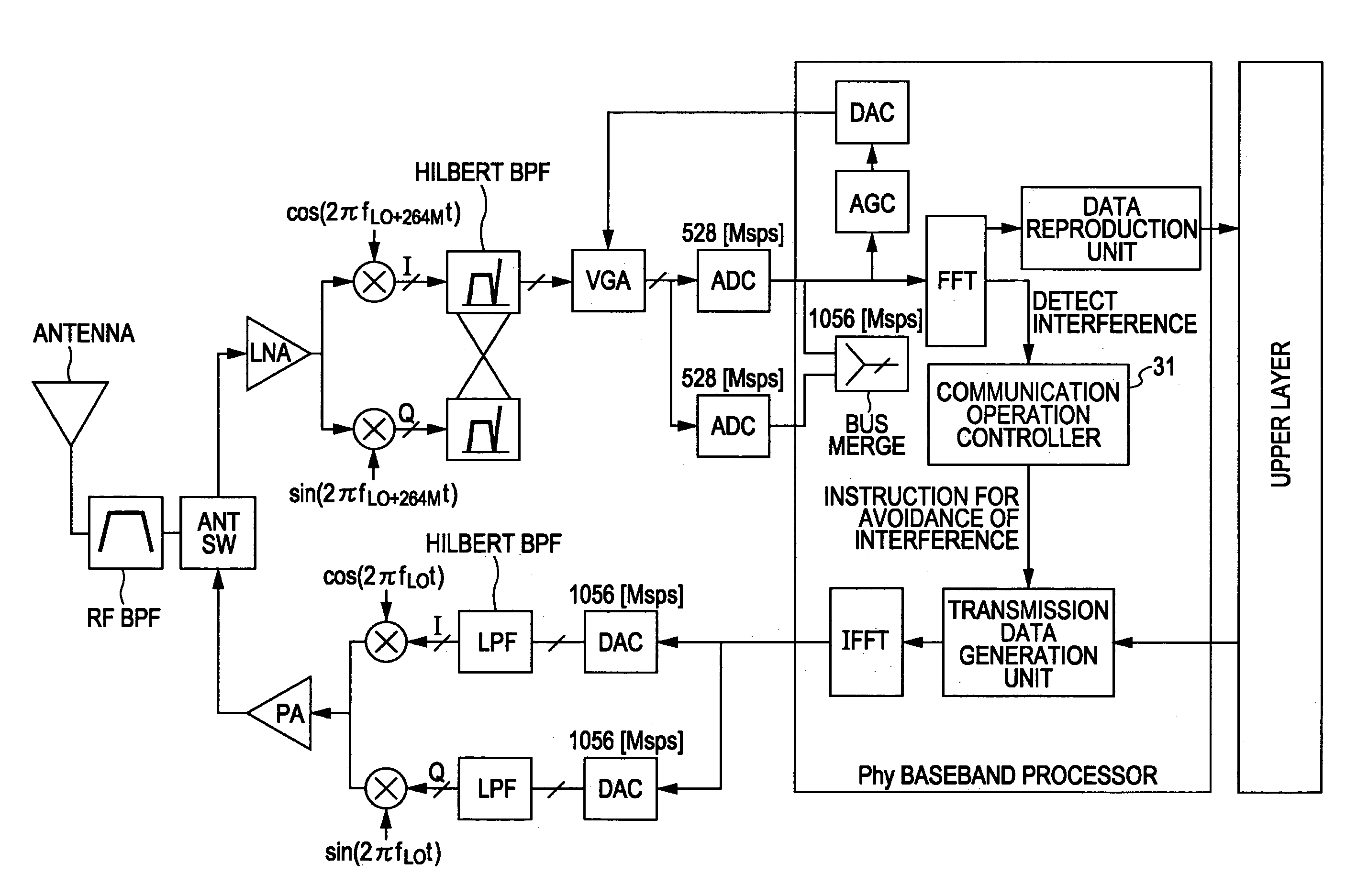
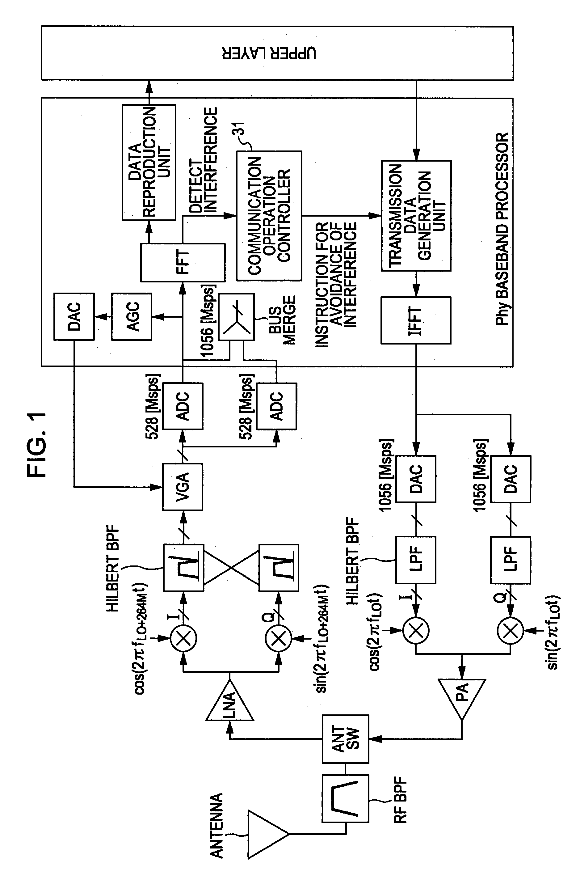
[0083]The present invention relates to a wireless communication apparatus that performs UWB communication in which an OFDM modulation method is adopted. More specifically, MB-OFDM communication in which the 3.1 GHz to 10.6 GHz frequency band defined by the FCC is divided into a plurality of subbands each having 528-MHz width and frequency hopping is performed between the subbands is performed. In addition, the DAA mechanism is implemented in the wireless communication apparatus according to an embodiment of the present invention in order to mitigate the level of interference to a different system caused by UWB transmission waves. The wireless communication apparatus examines whether a transmission signal from the different system exists in a UWB transmission band, and starts data transmission while avoiding the interference. Embodiments of the present invention will be described with reference to the drawings.

[0084]FIG. 1 shows a configuration of an MB-OFDM transceiver according to ...


PUM


Abstract

A wireless communication apparatus utilizing an orthogonal frequency division multiplexing communication method includes an antenna transmitting and receives a radio-frequency signal; a receiver frequency converter frequency-converting the radio-frequency signal into a baseband signal in accordance with a low-intermediate frequency method; an analog-to-digital converter converting the baseband signal into a digital signal; an orthogonal frequency division multiplexing demodulator acquiring a plurality of subcarriers in a frequency domain; a data reproduction unit reproducing data; a transmission data generator generating transmission data; an orthogonal frequency division multiplexing modulator performing orthogonal frequency division multiplexing modulation of the plurality of subcarriers; a digital-to-analog converter converting the digital orthogonal frequency division multiplexing signal into an analog signal; and a transmitter frequency converter converting the analog transmission baseband signal into a transmission radio-frequency signal in accordance with a zero-intermediate frequency method.

Description

CROSS REFERENCES TO RELATED APPLICATIONS[0001]The present invention contains subject matter related to Japanese Patent Application JP 2006-078773 filed in the Japanese Patent Office on Mar. 22, 2006, the entire contents of which are incorporated herein by reference.BACKGROUND OF THE INVENTION[0002]1. Field of the Invention[0003]The present invention relates to wireless communication apparatuses that adopt an orthogonal frequency division multiplexing (OFDM) modulation method and that perform ultra-wideband (UWB) communications in which transmission signals are spread over a wide band, and more particularly, to a multiband OFDM (MB-OFDM) wireless communication apparatus that performs UWB communications while performing frequency hopping (FP) for each OFDM symbol.[0004]More specifically, the present invention relates to wireless communication apparatuses that perform MB-OFDM communications while avoiding, in consideration of frequency use efficiency, interference with existing communi...

Claims


Application Information

Patent Timeline
IPC IPC(8): H04K1/10H04B1/713H04B1/715H04J11/00
CPCH04L27/2601H04B2001/7154
Inventor NAKAYAMA, TAKASHISUZUKI, MITSUHIRO
Owner SONY CORP
Why Eureka
Try Eureka