
Magnetic materials having superparamagnetic particles

a superparamagnetic particle and magnetic material technology, applied in the field of magnetic materials, can solve the problems of less than 1%) of memory applications, very small intrinsic magnetization damping, and interference constructively, and achieve the effect of reducing coercivity and increasing damping

Inactive Publication Date: 2007-09-27
GLOBALFOUNDRIES INC
View PDF9 Cites 12 Cited by
  • Summary
  • Abstract
  • Description
  • Claims
  • Application Information

AI Technical Summary

Benefits of technology

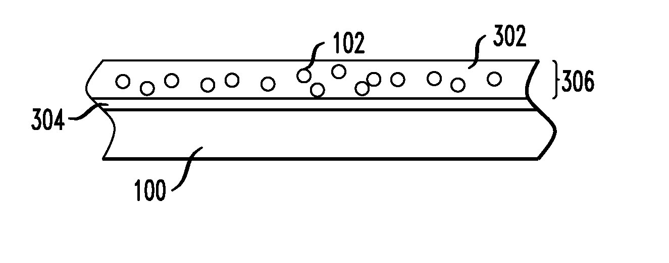
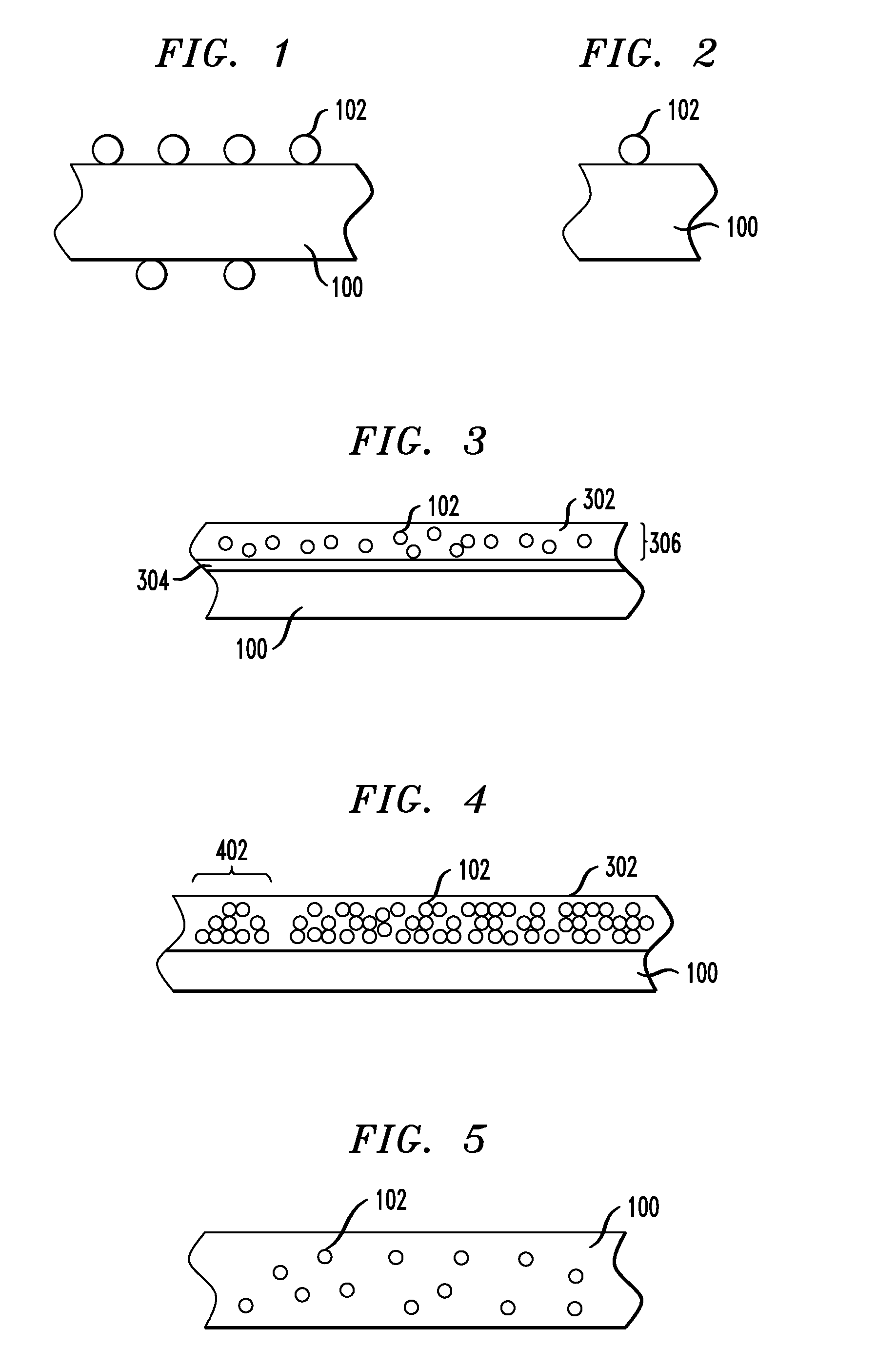
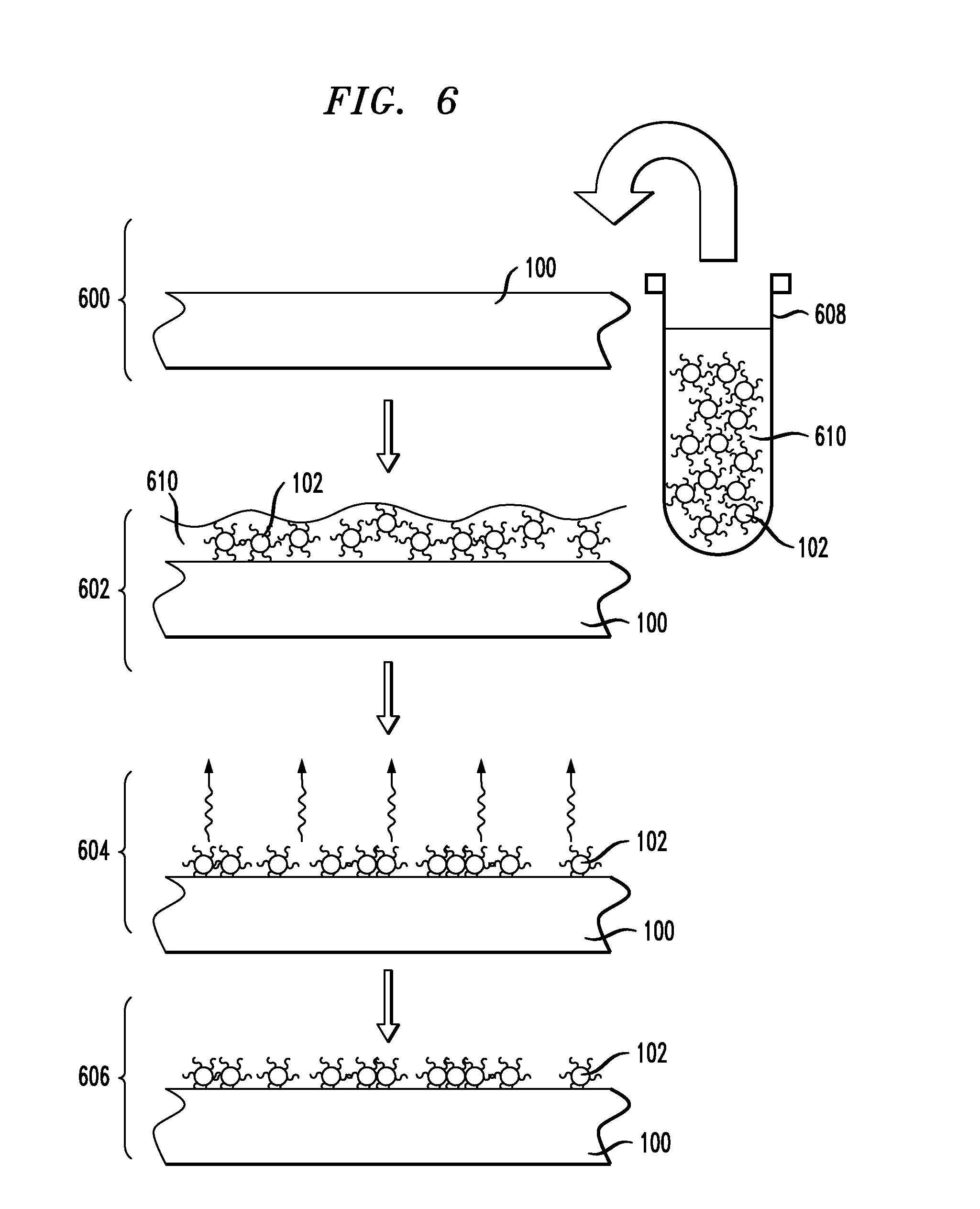
[0015] The present invention provides magnetic materials and uses thereof. In one aspect of the invention, a magnetic film is provided. The magnetic film comprises superparamagnetic particles on at least one surface thereof. The magnetic film may be patterned and may comprise a ferromagnetic material. The superparamagnetic particles may be coated with a non-magnetic polymer and / or embedded in a non-magnetic host material. The magnetic film may have increased damping and / or decreased coercivity.

Problems solved by technology

As magnetic devices are made smaller; and designed to switch faster, the challenge of getting the switched region to relax with certainty to a desired magnetization configuration arises.
However, the conducting ferromagnetic materials used in these devices, typically transition metal alloys, have very small intrinsic magnetization damping.
During the precession period, particularly during the initial stages where the amplitude is large, spin-waves, both thermally excited and those excited by the switching process and defects in the material, can interfere constructively to direct the magnetization to an equilibrium configuration other than the one intended.
Even a small probability of such a spurious switching event (i.e., less than 1%) is unacceptable for memory applications.
One challenge associated with magnetic switching devices, such as those employing small area structures, is that the shape anisotropy contribution to the switching field, assuming that the small magnetic element has an aspect ratio not equal to one in the plane of the device, increases inversely proportional to the thickness of the small magnetic element (perpendicular to the plane).
This effect calls fox the use of higher currents to generate the switching fields and brings about increased power consumption and increased heating.
These materials tend to be severely underdamped, whether in a bulk form, a thin film or a small lithographically defined element.

Method used


Image

  • Magnetic materials having superparamagnetic particles
  • Magnetic materials having superparamagnetic particles
  • Magnetic materials having superparamagnetic particles

Examples


example

[0068] A magnetic film was synthesized with superparamagnetic layers comprising superparamagnetic particles deposited on the surface thereof. The damping properties of the film were tested with FMR, as described above. The superparamagnetic particles used for the test comprised cobalt, and were formed with an average diameter of about nine nanometers. The magnetic film was made comprising Permalloy™, Ni81Fe19. The magnetic film was formed in the shape of a disk with a diameter of about 18 millimeters and having a thickness of about 30 nanometers. The damping properties of the film were tested at three stages of deposition of the superparamagnetic particles, namely, prior to deposition; after a first deposition and self-assembly of superparamagnetic particles; and after a second deposition and self-assembly of superparamagnetic particles of the second deposition on top of the first. The results are shown plotted in FIG. 9. FIG. 9 is a plot illustrating magnetic susceptibility as a fu...


PUM

PropertyMeasurementUnit
thicknessaaaaaaaaaa
thicknessaaaaaaaaaa
thicknessaaaaaaaaaa

Abstract

Magnetic materials and uses thereof are provided. In one aspect, a magnetic film is provided. The magnetic film comprises superparamagnetic particles on at least one surface thereof. The magnetic film may be patterned and may comprise a ferromagnetic material. The superparamagnetic particles may be coated with a non-magnetic polymer and / or embedded in a non-magnetic host material. The magnetic film may have increased damping and / or decreased coercivity.

Description

CROSS-REFERENCE TO RELATED APPLICATIONS [0001] This application is a continuation of U.S. patent application Ser. No. 10 / 459,112, filed on Jun. 10, 2003, incorporated by reference herein.FIELD OF THE INVENTION [0002] The present invention relates to magnetic materials and, more particularly, to magnetic materials having superparamagnetic particles associated therewith. BACKGROUND OF THE INVENTION [0003] A general trend in both storage and electronics has been to make devices smaller and faster. The same trend exists with magnetoelectronic “spintronic” devices, wherein the magnetic regions awe becoming ever smaller. Such devices rely, in some cases, on the switching of a region of magnetic material between two or more stable configurations of magnetization, and in other cases (e.g., magnetoresistive field sensors), on biasing of the magnetization away from a single equilibrium configuration by, and in some proportion to, the field being sensed. As magnetic devices are made smaller; a...

Claims


Application Information

Patent Timeline
Patent Type & Authority Applications(United States)
IPC IPC(8): G11B5/66H01L43/00G11C11/16H01F1/00H01F10/00H01F10/32H01F41/30H01L43/10
CPCB82Y25/00B82Y40/00G11C11/16H01L43/10H01F10/007H01F10/324H01F41/301H01F1/0063G11C11/161H10N50/85
Inventor INGVARSSON, SNORRI THORGEIRTROUILLOUD, PHILIP LOUISSUN, SHOUHENGKOCH, ROGER HILSENABRAHAM, DAVID WILLIAM
Owner GLOBALFOUNDRIES INC
Learn More