Photoelectrolysis cells, and related devices and processes

a photoelectrolysis and cell technology, applied in the field of photoelectrolysis cells, can solve the problems of inability to meet the needs of photoelectrolysis technology,

Inactive Publication Date: 2007-10-04
GENERAL ELECTRIC CO
View PDF8 Cites 19 Cited by
  • Summary
  • Abstract
  • Description
  • Claims
  • Application Information

AI Technical Summary

Benefits of technology

[0018] (i) exposing the photoelectrode to solar radiation, so as to initiate electrochemical oxidation and reduction reactions which result in the evolution of hydrogen at one of the electrodes; and

Problems solved by technology

The need for such technology is more urgent as the damaging effects of burning fossil fuels has become apparent.
However, photoelectrolytic processes continue to have serious drawbacks.
For example, the processes can be relatively slow and inefficient.
The poor efficiency is due in large part to the bandgap characteristic of the photocatalyst(s) employed in the photoelectrolytic cells.
Most known photocatalysts have bandgaps which are too large for the efficient photoelectrochemical splitting of water, i.e., only a small portion of the solar spectrum participates in photocatalysis.
(In the case of TiO2, the alignment of the band gap with the oxidation and reduction potential of water is not ideal for some electrolysis systems).
However, use of a large electrical bias diminishes the advantages of using solar radiation in the first place.
While tandem cells may sometimes provide greater photoelectrolytic efficiency, there are drawbacks associated with them as well.
For example, the cell structure can be complex, and difficult to produce.
Greater complexity often leads to higher manufacturing costs.
Moreover, some of the non-oxide types of tandem cells can be susceptible to photo-induced corrosion.

Method used


Image

  • Photoelectrolysis cells, and related devices and processes
  • Photoelectrolysis cells, and related devices and processes

Examples


Embodiment Construction

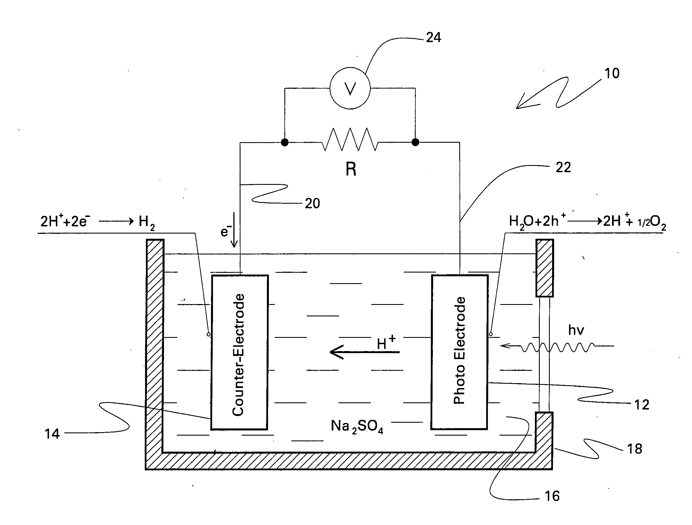
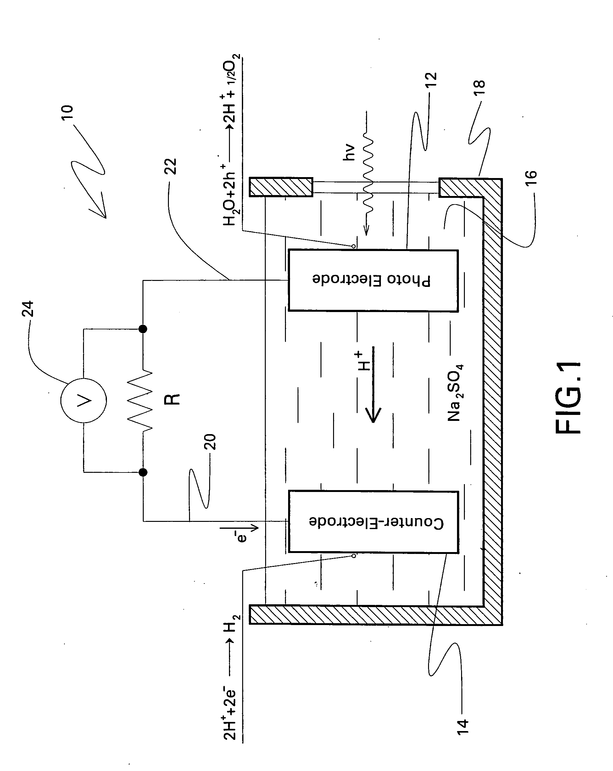
[0022] The photoelectrolysis cell of the present invention can assume a number of structural configurations. Photoelectrolytic cells are described in many references. Non-limiting examples include U.S. Pat. No. 4,090,933 (Nozik) and U.S. Pat. No. 4,172,925 (Chen et al), which are both incorporated herein by reference. Typically, the photoelectrolysis cell includes a photoelectrode and a counter-electrode, which can be connected to each other in various ways. For example, each electrode could be partially or fully immersed in a liquid electrolyte, and spaced from the other. The electrodes could also be incorporated into a conventional electrical circuit with suitable conductors, as depicted in FIG. 1 (discussed below).

[0023] However, other conventional electrode structures are also possible. For example, the photoelectrode and the counter-electrode could be physically attached to each other, e.g., without the need for wire connections between them. In some cases, the photoelectrode ...


PUM

PropertyMeasurementUnit
bandgap energyaaaaaaaaaa
pHaaaaaaaaaa
transparentaaaaaaaaaa

Abstract

A photoelectrolysis cell is described herein. The cell includes a photoelectrode based on a material having the general formula (Ln1−xMx)(Nb1−yTay)O1+xN2−x. Ln is at least one lanthanide element; M is at least one alkaline earth metal; 0≦x≦0.99; and 0≦y≦1. The photoelectrolysis cell further includes a counter-electrode formed from at least one metal or metallic alloy. An electrolyte which is in contact with both the photoelectrode and the counter-electrode is another component of the cell, along with a means for collecting hydrogen produced by the cell. A related process for producing hydrogen in a photoelectrolysis cell is also described.

Description

BACKGROUND OF THE INVENTION [0001] This invention relates generally to the production of hydrogen and oxygen by the electrolysis of water. In some specific embodiments, the invention is directed to the production of hydrogen by the photoelectrolysis of water, using solar radiation. [0002] The conversion of sunlight and water into a clean, high-efficiency chemical fuel has been of great interest for a number of years. The need for such technology is more urgent as the damaging effects of burning fossil fuels has become apparent. The photolysis of water to yield hydrogen and oxygen has been demonstrated, via the visible light illumination of Group II-sulfides and selenides, such as CdS, CdSe, ZnS, and the like. Water has also been photolyzed under ultraviolet light illumination, using compounds such as TiO2, BaTiO3, and ZnO. [0003] Photoelectrolytic devices are in many ways similar to photovoltaic devices, which include a p-n junction. In the case of photoelectrolytic devices, the p-n...

Claims


Application Information

Patent Timeline
Patent Type & Authority Applications(United States)
IPC IPC(8): C25B1/00C25B11/04
CPCC25B1/003Y02E60/368Y02E60/364C25B1/55Y02E60/36
Inventor MCNULTY, THOMAS FRANCISSETLUR, ANANT ACHYUT
Owner GENERAL ELECTRIC CO
Why Eureka
Try Eureka