
Pulsed Synchronized Laser Cutting of Stents

a synchronized laser and stent technology, applied in the field of pulsed laser cutting of stents, can solve the problem of putting more laser power in the tight, and achieve the effect of low heat build-up and high resolution

Inactive Publication Date: 2007-10-04
ABBOTT CARDIOVASCULAR
View PDF9 Cites 86 Cited by
  • Summary
  • Abstract
  • Description
  • Claims
  • Application Information

AI Technical Summary

Benefits of technology

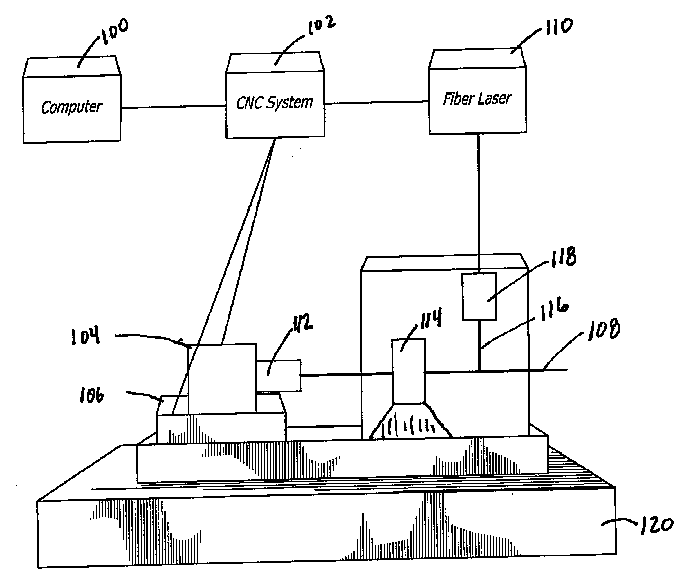
[0015] In one embodiment of the invention, in order to minimize the heat build-up, which prevents thermal distortion, uncontrolled burnout of the stent material, and damage due to excessive heat, a diode pumped fiber laser is utilized. The laser is “pulsed,” in that a pulse generator causes the laser to operate in pulses. Broadly speaking, the laser pulsing is synchronized with the cutting speed. The average laser power is thereby reduced in the slower cutting areas. Consequently, heat build up in the slower cutting areas is also reduced. It is thereby possible to make smooth, narrow cuts in the stainless steel tubes in very fine geometries without damaging the narrow struts that make up the stent structure and, in some embodiments, to speed up the rate at which the stent is cut.
[0017] In this embodiment, the numerical controller is also in communication with the pulsed fiber laser and is configured to send pulse control information to the pulsed fiber laser. The numerical controller is configured to cause average laser power to decrease by decreasing frequency of laser pulses as stent cutting speed decreases, and to cause average laser power to increase by increasing frequency of laser pulses as stent cutting speed increases.
[0023] Hence, the new and improved method and apparatus for direct laser cutting of metal stents, in accordance with the present invention, makes accurate, reliable, high resolution, expandable stents with patterns having smooth, narrow cuts and very fine geometries, with minimal heat build-up during the stent-cutting process.

Problems solved by technology

As a result, cutting systems in which the laser runs at constant pulse frequencies tend to put more laser power in the tight bends and turns.

Method used


Image

  • Pulsed Synchronized Laser Cutting of Stents
  • Pulsed Synchronized Laser Cutting of Stents
  • Pulsed Synchronized Laser Cutting of Stents

Examples


Embodiment Construction

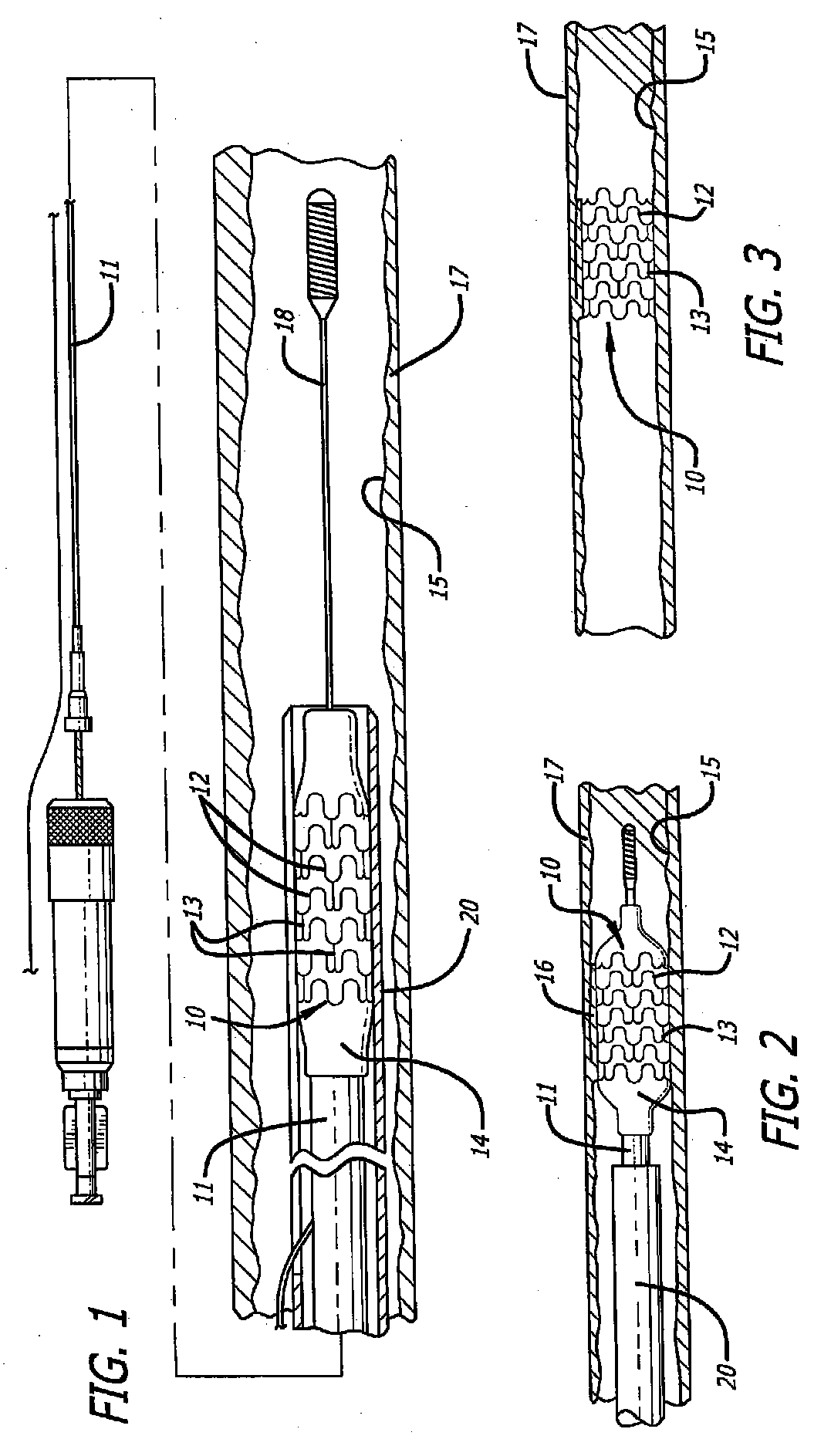
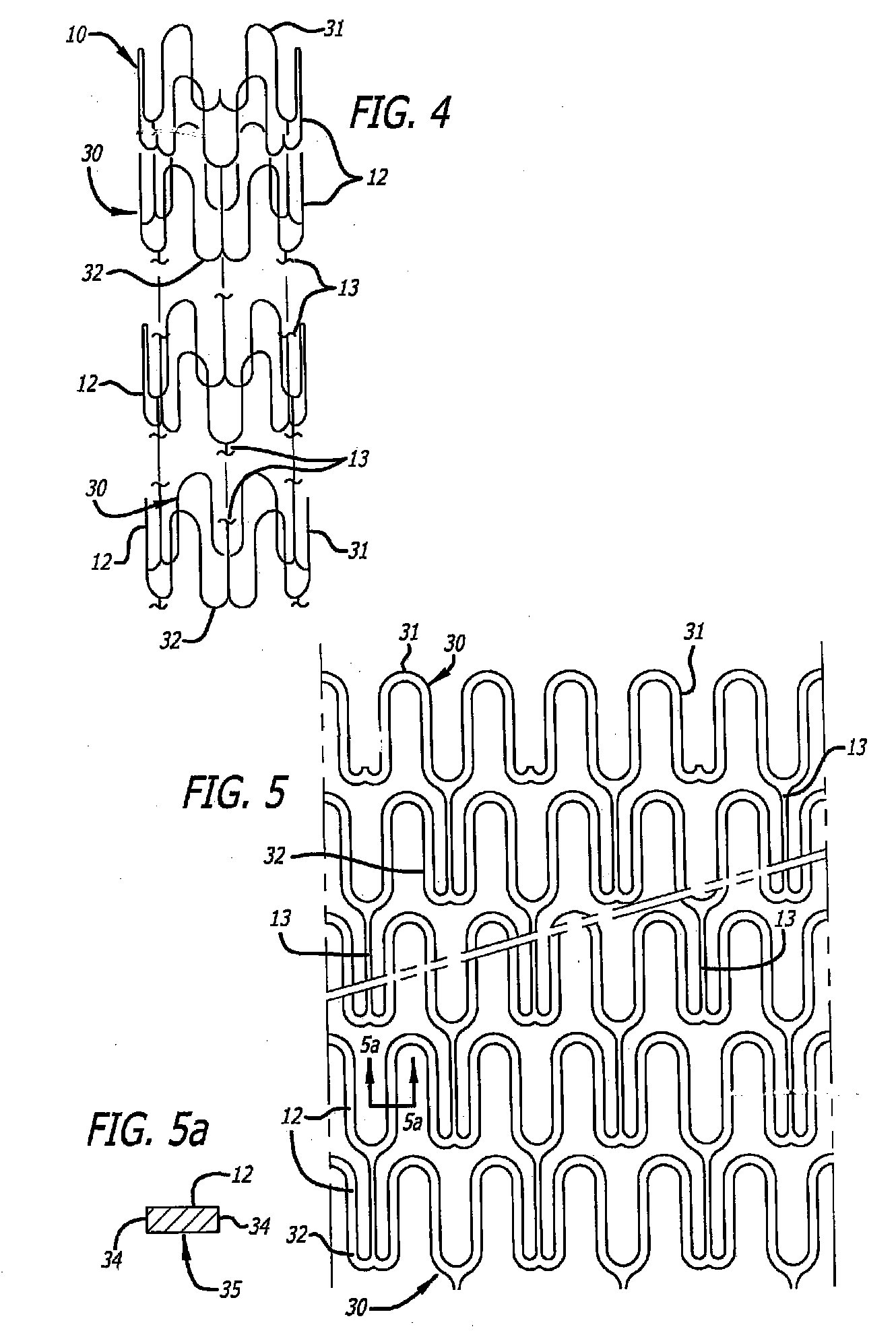
[0036] Referring now to the drawings, and particularly to FIG. 1, there is shown a stent 10 that is mounted onto a delivery catheter 11. The stent 10 is simply an example of one of a great many different stent designs and other medical devices that can be cut using the technique and apparatus of the present invention. Generally, a stent is a high precision patterned tubular device. A stent typically comprises a plurality of radially expanded cylindrical elements 12 disposed generally coaxially and interconnected by elements 13 disposed between adjacent cylindrical elements. The delivery catheter has an expandable portion or balloon 14 for expanding of the stent within an artery 15. Alternatively, the stent may be self-expanding, for example.

[0037] The typical delivery catheter 11 onto which the stent 10 is mounted is essentially the same as a conventional balloon dilatation catheter for angioplasty procedures. The balloon 14 may be formed of suitable materials such as polyethylene,...


PUM

PropertyMeasurementUnit
Diameteraaaaaaaaaa
Diameteraaaaaaaaaa
Poweraaaaaaaaaa

Abstract

A system for pulsed synchronized laser cutting of stents and / or other medical products includes a numerical controller and a machine for moving a tube of material during cutting. A pulsed fiber laser is configured to cut the tube into, for example, a stent, the numerical controller being in communication with the machine and configured to send movement control information to the machine. The numerical controller may also receive movement speed information from the machine. The numerical controller is also in communication with the pulsed fiber laser and is configured to send pulse control information to the pulsed fiber laser. The numerical controller is configured to cause average laser power to decrease by decreasing frequency of laser pulses as stent cutting speed decreases, and to cause average laser power to increase by increasing frequency of laser pulses as stent cutting speed increases.

Description

BACKGROUND OF THE INVENTION [0001] This invention relates generally to improvements in the manufacture of expandable metal stents and, more particularly, to new and improved efficient methods and apparatus for direct laser cutting of metal stents. [0002] Stents are expandable endoprosthesis devices which are adapted to be implanted into a patients body lumen, such as a blood vessel, to maintain the patency of the vessel. These devices are typically used in the treatment of atherosclerotic stenosis in blood vessels and the like. [0003] In the medical arts, stents are generally tubular-shaped devices which function to hold open a segment of a blood vessel or other anatomical lumen. They are particularly suitable for use to support and hold back a dissected arterial lining which can occlude the fluid passageway. [0004] Various means have been provided to deliver and implant stents. One method frequently described for delivering a stent to a desired intraluminal location includes mounti...

Claims


Application Information

Patent Timeline
IPC IPC(8): B23K26/38
CPCA61F2/91B23K26/0823B23K26/0626
Inventor KLEINE, KLAUSFOX, WILLIAM JASONPALLEY, SCOTT
Owner ABBOTT CARDIOVASCULAR
Learn More