Extreme ultra violet light source device

a light source device and ultra violet technology, applied in the field of extreme ultra violet light source devices, can solve the problems of sputtered reflection surfaces of mirrors (mo/si multi-layered films), and high cost of mirrors

Active Publication Date: 2007-10-04
GIGAPHOTON
View PDF11 Cites 47 Cited by
  • Summary
  • Abstract
  • Description
  • Claims
  • Application Information

AI Technical Summary

Benefits of technology

[0014]The present invention has been achieved in view of the above-mentioned problems. A purpose of the present invention is to efficiently eject charged particles such as ions emitted from plasma in an extreme ultra violet light source device of a laser produced plasma type.
[0016]According to the present invention, the charged particles such as ions emitted from plasma can be led out in a desired direction by the action of the asymmetric magnetic field formed by the magnetic field forming means. Accordingly, the charged particles such as ions can be promptly eliminated from the vicinity of the EUV collector mirror or the plasma emission point, and therefore, the contamination and damage on the EUV collector mirror and the rise in concentration of ions, etc. can be suppressed.

Problems solved by technology

In the LPP type EUV light source device, there is a problem of the influence by charged particles such as fast ions emitted from plasma.
This is because the EUV collector mirror 905 is located relatively near the plasma emission point (the position where the laser beam is applied to the target material), and thus, the fast ions and soon collide with the EUV collector mirror 905 and the reflection surface of the mirror (Mo / Si multilayered film) is sputtered and damaged.
For the purpose, high flatness is required for the reflection surface of the EUV collector mirror 905, and the mirror becomes very expensive.
Since the target gas absorbs the EUV light radiated from the plasma, a problem is caused that the available EUV light decreases as the concentration rises.
Therefore, in consideration of the interference with the filter, the coupling mechanism and so on, it is difficult to provide the mechanism for ejecting ions, etc. at the side opposite to the collector mirror.
On the other hand, in the case where the position of the ejection mechanism, especially, the ejection opening to be formed in the chamber is inappropriate, the ejection speed of ions, etc. becomes lower and the concentration of ions, etc. rises within the chamber.

Method used


Image

  • Extreme ultra violet light source device
  • Extreme ultra violet light source device
  • Extreme ultra violet light source device

Examples


first embodiment

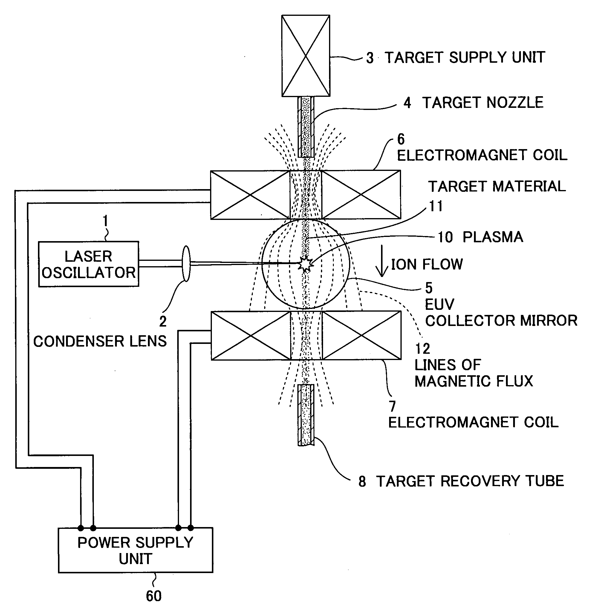
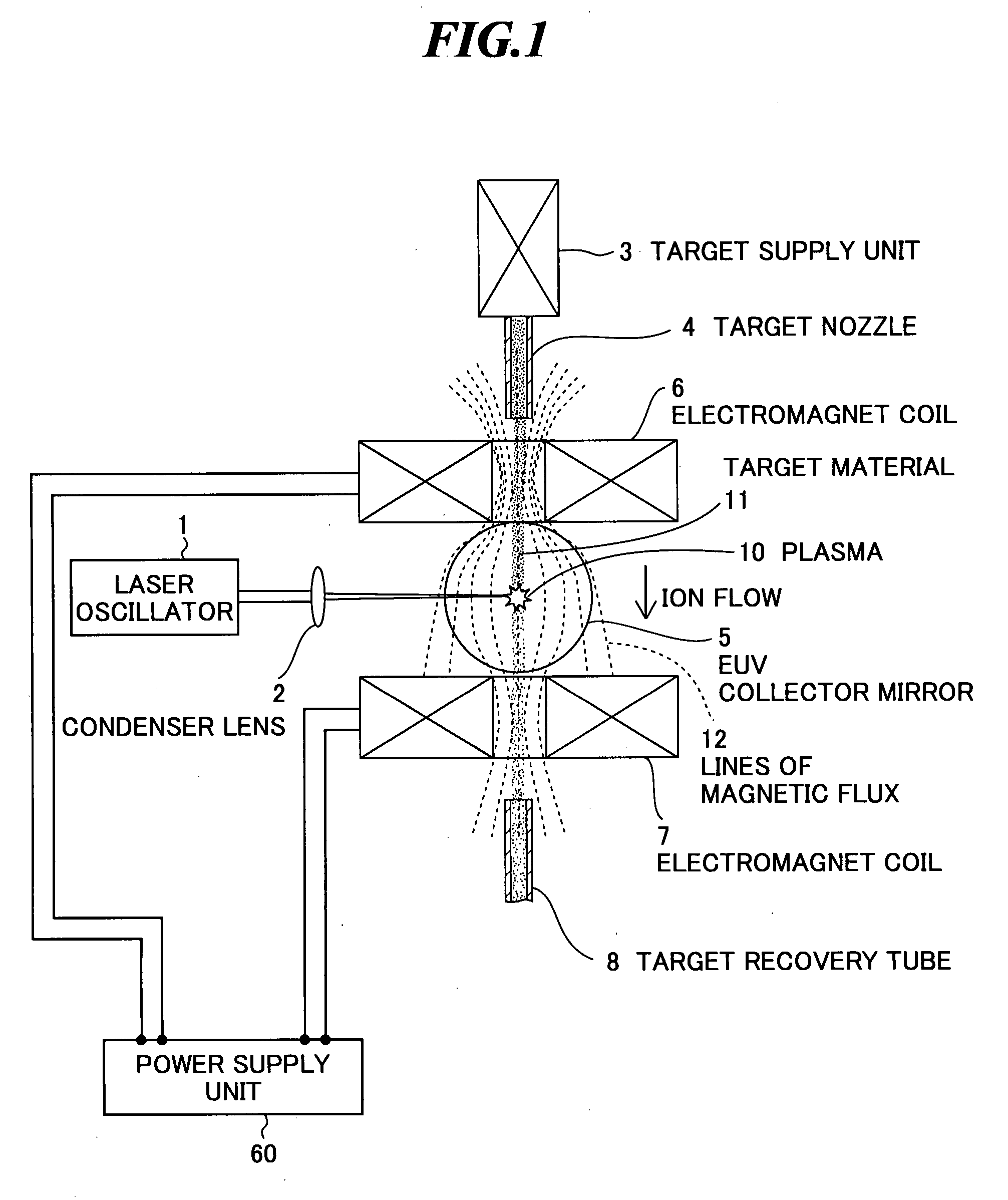
[0040]FIG. 1 is a sectional view showing a configuration of an extreme ultra violet (EUV) light source device according to the present invention. The EUV light source device according to the embodiment employs a laser produced plasma (LPP) type that generates EUV light by applying a laser beam to a target material for excitation. As shown in FIG. 1, the EUV light source device includes a laser oscillator 1, a condenser lens 2, a target supply unit 3, a target nozzle 4, an EUV collector mirror 5, electromagnets 6 and 7, and a target recovery tube 8. The electromagnets 6 and 7 are connected via wiring to a power supply unit 60 for supplying electric currents to the electromagnets 6 and 7.

[0041]The laser oscillator 1 is a laser light source capable of pulse oscillation at a high repetition frequency, and generates a laser beam to be applied to a target material for excitation. Further, the condenser lens 2 constitutes collector optics that collects the laser beam emitted from the laser...

second embodiment

[0061]Next, an extreme ultra violet light source device according to the present invention will be explained by referring to FIGS. 3A and 3B. FIG. 3A is a schematic view showing the extreme ultra violet light source device according to the embodiment, and FIG. 3B is a sectional view along 3B-3B′ shown in FIG. 3A.

[0062]In the embodiment, the positions of the target nozzle 4 and the target recovery tube 8 are changed compared to the configuration shown in FIG. 1. That is, the target nozzle 4 and the target recovery tube 8 are located between the electromagnets 6 and 7 in the horizontal direction as shown in FIGS. 3A and 3B. The positions and orientation of the target nozzle 4 and the target recovery tube 8 are not especially limited as long as the target material 1 injected from the target nozzle 4 can pass the plasma emission point and avoid interference with other components including the EUV collector mirror 5 and the electromagnets 6 and 7. However, in order to reduce the collisio...

third embodiment

[0067]Next, an extreme ultra violet light source device according to the present invention will be explained by referring to FIGS. 4A and 4B. FIG. 4A is a schematic view showing the extreme ultra violet light source device according to the embodiment, and FIG. 4B is a sectional view along the dashed-dotted line 4B-4B′ shown in FIG. 4A.

[0068]In the extreme ultra violet light source device according to the embodiment, a part of the constituent components shown in FIGS. 3A and 3B is located within the vacuum chamber 20. That is, the condenser lens 2, a part of the target supply unit 3, the target nozzle 4, the EUV collector mirror 5, the electromagnets 6 and 7, and the target recovery tube 8 of the constituent components are located within the vacuum chamber 20. The operation of and the arrangement relationship among these constituent components are the same as those in the second embodiment. Further, the extreme ultra violet light source device according to the embodiment further has ...


PUM


Abstract

An extreme ultra violet light source device of a laser produced plasma type, in which charged particles such as ions emitted from plasma can be efficiently ejected. The extreme ultra violet light source device includes: a target nozzle that supplies a target material; a laser oscillator that applies a laser beam to the target material supplied from the target nozzle to generate plasma; collector optics that collects extreme ultra violet light radiated from the plasma; and a magnetic field forming unit that forms an asymmetric magnetic field in a position where the laser beam is applied to the target material.

Description

BACKGROUND OF THE INVENTION[0001]1. Field of the Invention[0002]The present invention relates to an extreme ultra violet light source device, which is used as a light source of exposure equipment, for generating extreme ultra violet (EUV) light by applying a laser beam to a target.[0003]2. Description of a Related Art[0004]Recent years, photolithography has made rapid progress to finer fabrication with finer semiconductor processes. In the next generation, microfabrication of 100 nm to 70 nm, further, microfabrication of 50 nm or less will be required. For example, in order to fulfill the requirement for microfabrication of 50 nm or less, the development of exposure equipment with a combination of an EUV light source of about 13 nm in wavelength and a reduced projection reflective optics is expected.[0005]As the EUV light source, there are three kinds of light sources, which include an LPP (laser produced plasma) light source using plasma generated by applying a laser beam to a targ...

Claims


Application Information

Patent Timeline
Patent Type & Authority Applications(United States)
IPC IPC(8): G21G4/00
CPCH05G2/003G21K5/00H05G2/005H05G2/008
Inventor KOMORI, HIROSHIUENO, YOSHIFUMISOUMAGNE, GEORG
Owner GIGAPHOTON
Why Eureka
Try Eureka