Alignment method

a technology of alignment layer and alignment angle, applied in non-linear optics, instruments, optics, etc., can solve the problems of uneven alignment, decreased throughput, and increased consumption of material and manpower, so as to reduce manufacturing costs, prevent uneven alignment, and improve the yield of alignment of alignment layer.

Inactive Publication Date: 2007-10-04
CHUNGHWA PICTURE TUBES LTD
View PDF7 Cites 1 Cited by
  • Summary
  • Abstract
  • Description
  • Claims
  • Application Information

AI Technical Summary

Benefits of technology

[0010] Accordingly, the present invention is directed to provide an alignment method, which can efficiently prevent uneven alignment to improve the yield of alignment of the alignment layer and reduce the manufacturing cost.

Problems solved by technology

However, the distance estimated based on the average length is not precise if the lengths of the alignment cloth on the roller are too different.
However, when the operator is replacing the alignment cloth and the roller, not only will it interrupt the whole manufacturing flow, and the throughput is accordingly decreased, but the consumption of material and manpower will also be increased.
When the driving torque exceeds a tolerable range, which means the length of the alignment cloth is too different from the average length, the depth the alignment cloth pressed into the alignment layer material is either too deep or too shallow.
But usually the distance is adjusted manually, which consumes manpower and may results in a situation that the adjusted distance still cannot meet the actual requirement due to human error.

Method used


Image

  • Alignment method
  • Alignment method
  • Alignment method

Examples


first embodiment

The First Embodiment

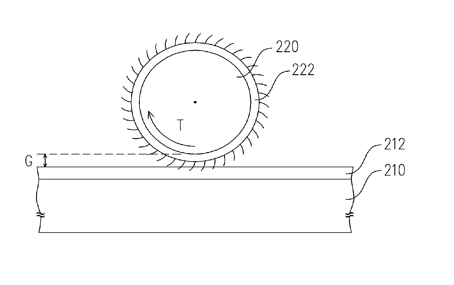
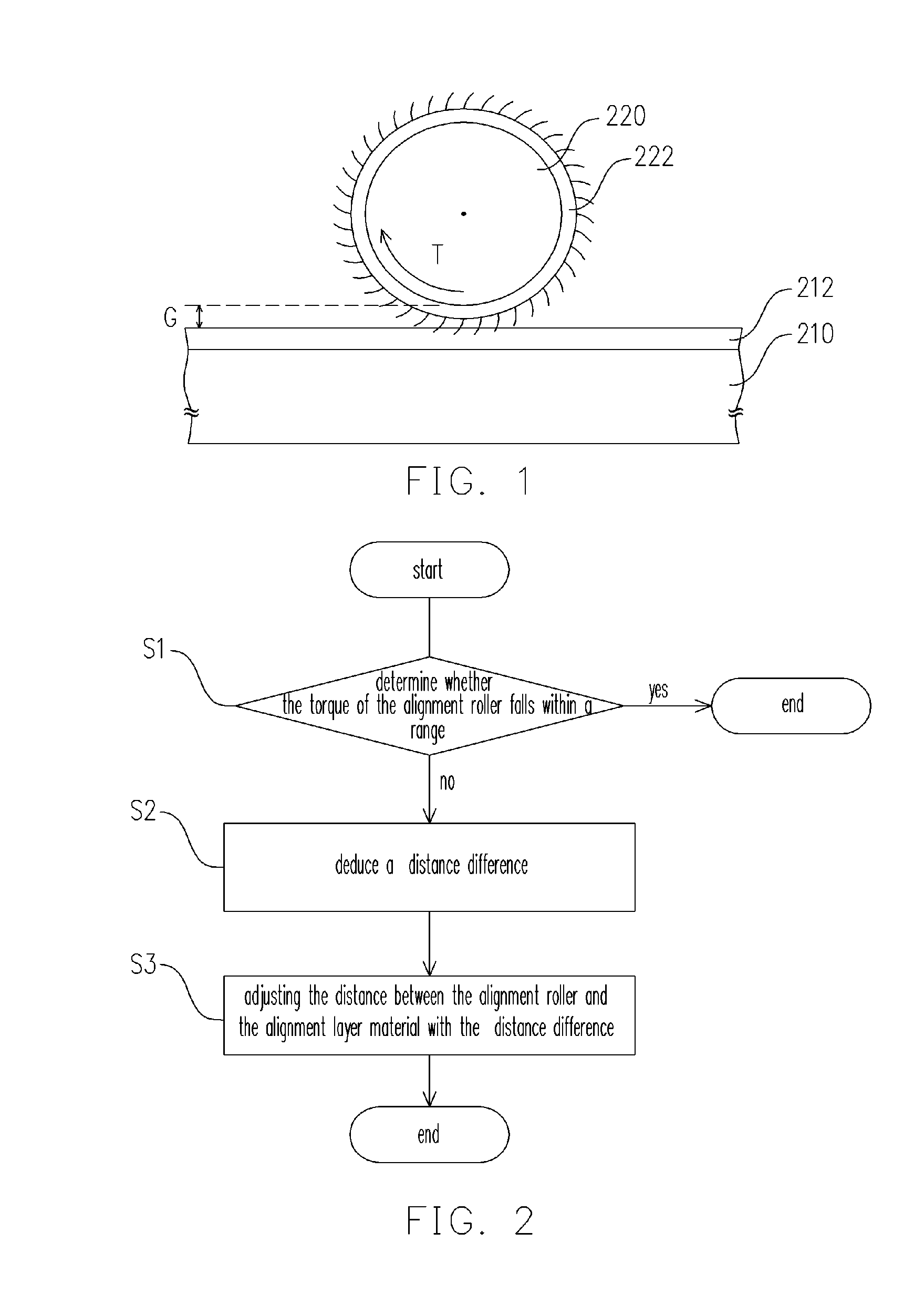
[0031]FIG. 1 is a profile view illustrating how to align the alignment layer material according to the present invention. Referring to FIG. 1, first, an alignment layer material 212 disposed on a substrate 210 is provided. Wherein, the alignment layer material 212 includes an organic material or inorganic material. Some typical inorganic materials are, for example, silicon carbide (SiC) or silicon oxide (SiO2), and the organic materials are, for example, polyimide compound. Generally speaking, the substrate 210 may be a color filter substrate or active device array substrate.

[0032] Next, a rubbing medium 222 is disposed on the surface of an alignment roller 220 of an alignment machine (not shown). To simplify the figure and the description, only the alignment roller 220 is shown here. Furthermore, the surface of the alignment roller 220 is at a distance G from the surface of the alignment layer material 212. Generally speaking, the rubbing medium 222 can be divi...

second embodiment

The Second Embodiment

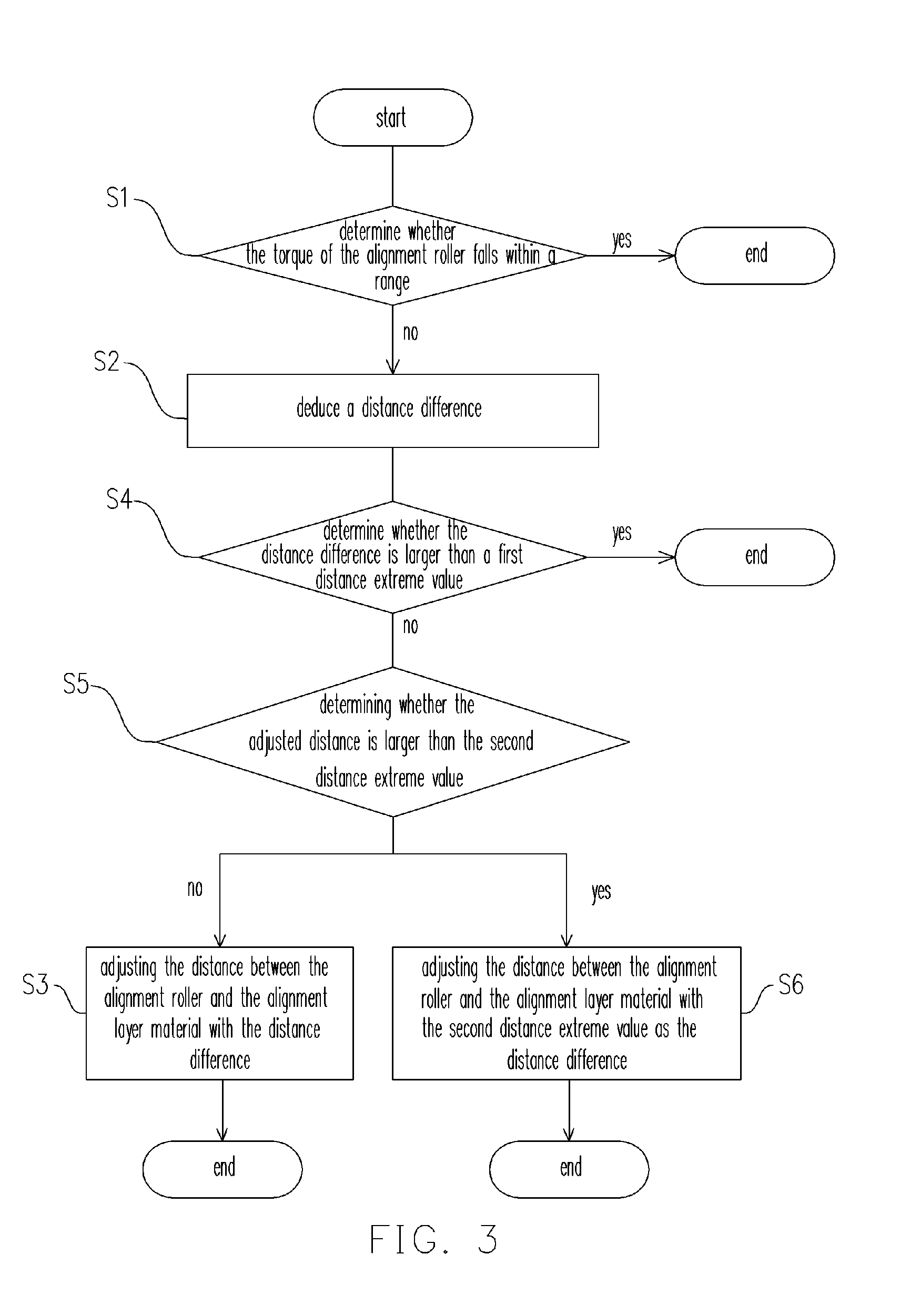
[0040] In addition to the main flow described in the first embodiment (as shown in FIG. 2), other flows may also be added into the alignment method of the present invention to meet the requirements of actual situations. The present embodiment is similar to the second embodiment, wherein the main difference is: in the present embodiment, some processes are added to meet the requirements of the actual situation after the distance difference AG has been deduced. This will be described in detail below.

[0041]FIG. 3 is a flowchart illustrating the alignment method in the second embodiment of the present invention. Referring to FIG. 3, before adjusting the distance G based on the distance difference AG (step S3), the following steps are further included: first, the operator can set a first distance extreme value D1 based on the thickness of the rubbing medium 222, wherein the first distance extreme value D1 is, for example, 1.8 millimeters; then, step S4 is executed t...


PUM

PropertyMeasurementUnit
first distanceaaaaaaaaaa
second distanceaaaaaaaaaa
distanceaaaaaaaaaa

Abstract

An alignment method is described. First, an alignment layer material disposed on a substrate is provided. Then, a rubbing medium disposed on a surface of an alignment roller is provided, and the surface of the alignment roller is at a distance from the surface of the alignment layer material. The rubbing medium is used to align the alignment layer material, and the alignment roller is suitable for being driven by a torque and maintaining a particular rotating speed. There is a rate between the distance and the torque. When the torque of the alignment roller is larger or smaller than the range, the distance corresponding to the torque is calculated based on the rate. A distance difference value is deduced from the distance corresponding to the torque. Then, the distance is adjusted with the distance difference value.

Description

BACKGROUND OF THE INVENTION [0001] 1. Field of Invention [0002] The present invention relates to an alignment method. More particularly, the present invention relates to an alignment method which can effectively improve uneven alignment of an alignment layer. [0003] 2. Description of Related Art [0004] Nowadays, the development of multimedia technology mainly benefits from the development of semiconductor devices or display apparatuses. As to displays, LCD panels, having such characteristics as high resolution, space utilization, low power consumption, no radiation etc., have become the mainstream of display products in the market. A typical LCD panel mainly comprises two substrates and a liquid crystal layer disposed between the two substrates. Regardless of an active matrix LCD or a passive matrix LCD, alignment layers are disposed on both substrates thereof. The main function of the alignment layers is to align the liquid crystal molecules so that the liquid crystal molecules rep...

Claims


Application Information

Patent Timeline
Patent Type & Authority Applications(United States)
IPC IPC(8): G02F1/1337
CPCG02F1/133784
Inventor CHEN, CHEIN-WENCHUANG, HONG-WENCHANG, KENG-HAOLIN, WEN-JHY
Owner CHUNGHWA PICTURE TUBES LTD
Why Eureka
Try Eureka