Condenser microphone circuit

Inactive Publication Date: 2007-10-04
AUDIO-TECHNICA
View PDF5 Cites 14 Cited by
  • Summary
  • Abstract
  • Description
  • Claims
  • Application Information

AI Technical Summary

Benefits of technology

[0019]A switch switches the values of the load resistance of the impedance converter so that the impedance converter may function effectively corresponding to a supply voltage when using the phantom power supply and a supply voltage when using the built-in battery power supply. Since the switch is an optical switch for turning on/off optical coupling relationship and cuts off an electrical and electromagnetic coupling, a high frequency current attempting to penetrate via the phantom power supply line is cut off by means of the optical switch, so that the high frequency current may not reach the impedance convert

Problems solved by technology

In contrast, in the case of a business-use condenser microphone, if it is operated only with a battery as a built-in power supply, when the battery is exhausted, it may not be used continuously and thus the reliability can not be maintained.
On the contrary, if the

Method used


Image

  • Condenser microphone circuit
  • Condenser microphone circuit
  • Condenser microphone circuit

Examples


Embodiment Construction

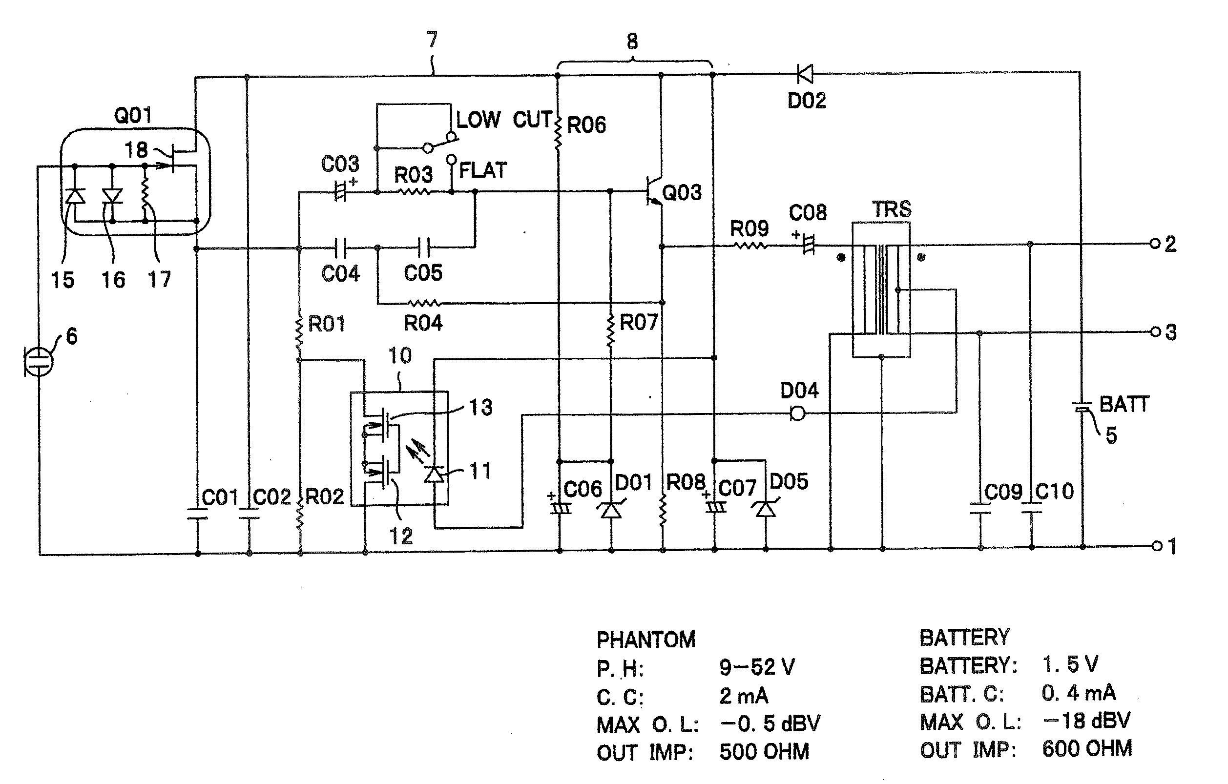
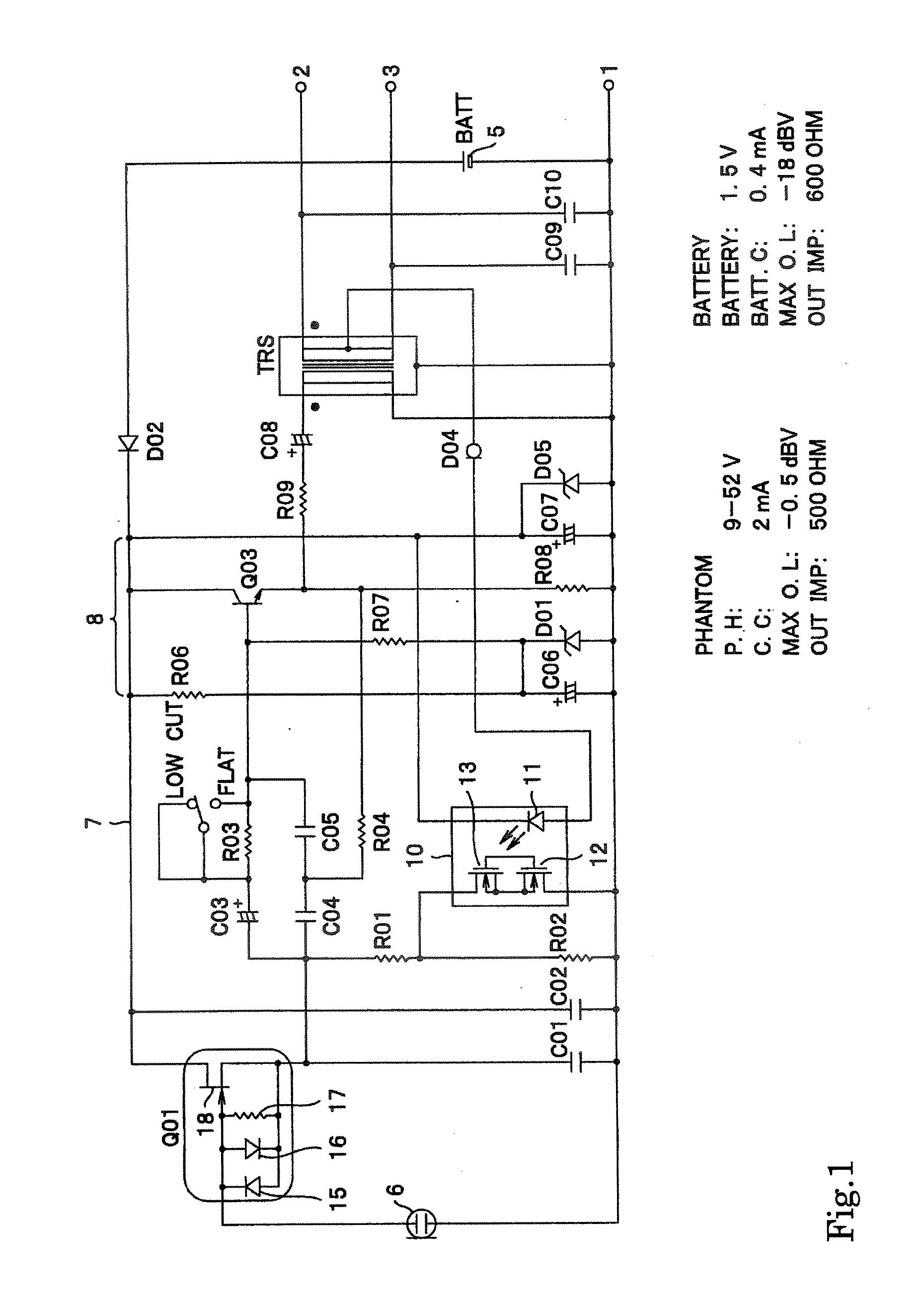
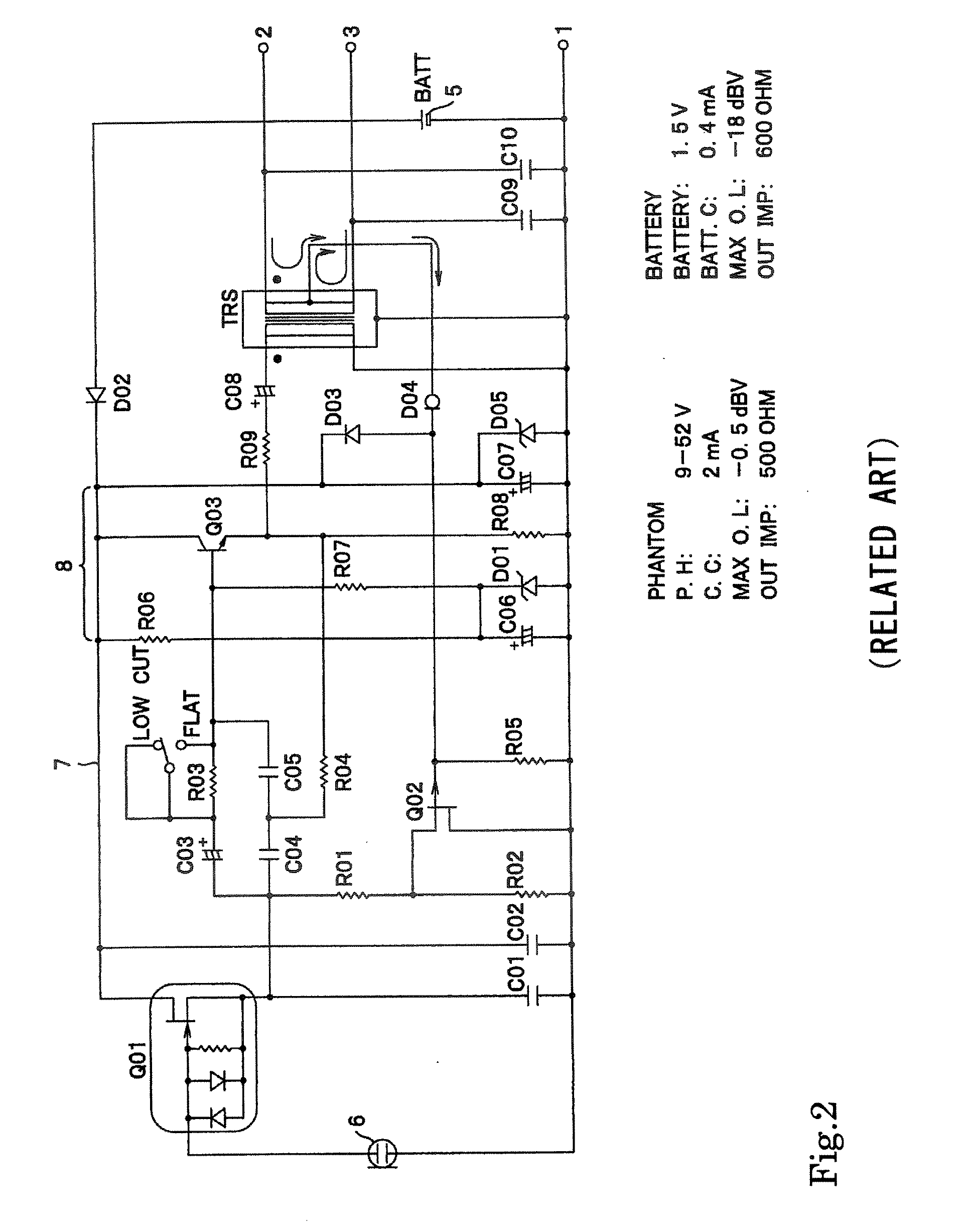
[0023]Hereinafter, an embodiment of a condenser microphone circuit according to the present invention will be described with reference to the drawings. The same reference numerals and symbols are given to the same components as those of the conventional example shown in FIG. 2.

[0024]In FIG. 1, reference numeral 5 denotes a built-in battery power supply, 6 denotes a condenser type electro-acoustic transducer element, 7 denotes a power supply line, 8 denotes a buffer amplifier, 10 denotes an optical switch, reference symbol Q01 denotes an impedance conversion element, and TRS denotes a transformer, respectively. As for a secondary winding of the transformer TRS, one end is connected to a hot side terminal pin 2, and the other end is connected to a cold side terminal pin 3. The terminal pin 2 and terminal pin 3 are connected to an output cord via a three pin type connector that complies with the EIAJ Standard, for example, and another terminal pin 1 is connected to the earth line of th...


PUM


Abstract

In a condenser microphone which selectively uses a phantom power supply and a built-in battery power supply, and which switches load resistance elements of an impedance converter corresponding to a selected power supply, a noise due to the high frequencies is prevented from occurring even if a cellular phone or the like is used in the vicinity. The condenser microphone includes: a condenser type electro-acoustic transducer element; an impedance converter that converts an output impedance of the electro-acoustic transducer element; load resistance elements of the impedance converter; a phantom power supply and a built-in battery power supply for operating the impedance converter; a switch that switches the values of the load resistance between at the time of using the phantom power supply and at the time of using the built-in battery power supply, wherein the switch is an optical switch that turns on/off optical coupling. The optical switch is switched so that the value of the load resistance is larger at the time of using the phantom power supply than at the time of using the built-in battery power supply.

Description

BACKGROUND OF THE INVENTION[0001]1. Field of the Invention[0002]The present invention relates to a condenser microphone circuit, and in particular to a condenser microphone circuit capable of operating by switching a phantom power supply and a battery, which is a built-in power supply.[0003]2. Related Background of the Invention[0004]In a condenser microphone, an impedance converter using an FET (Field Effect Transistor, and hereinafter the same) or the like is used because the impedance of a condenser microphone unit, which is an electro-acoustic transducer, is high. A power supply is required to operate this impedance converter. The power supplies for the condenser microphone include a power supply that is built-in within a microphone, i.e., typically a battery, and a mixer or a phantom power supply for supplying power from the outside. The above-described phantom power source is supplied to a microphone via an output cord of the microphone as specified in Standard of Electronic I...

Claims


Application Information

Patent Timeline
IPC IPC(8): H04R3/00H04R25/00
CPCH04R3/00
Inventor AKINO, HIROSHI
Owner AUDIO-TECHNICA
Why Eureka
Try Eureka