
Intraocular lens implant

a technology of intraocular lens and implant, which is applied in the field of intraocular lens implants, can solve the problems of inability to accommodate, and achieve the effects of high refractive index, high elasticity, and similar siz

Inactive Publication Date: 2007-10-04
THE BOARD OF TRUSTEES OF THE LELAND STANFORD JUNIOR UNIV
View PDF8 Cites 43 Cited by
  • Summary
  • Abstract
  • Description
  • Claims
  • Application Information

AI Technical Summary

Benefits of technology

"The present invention provides a hydrogel-based intraocular lens (IOL) implant that can covalently attach to a lens capsule on implantation into an eye. The covalent binding of the IOL to the lens capsule is preferably mediated by active functional groups covalently linked to a surface of a hydrogel, for example through a photoreactive azide. The active functional groups are preferably N-hydroxysuccinimide functional groups tethered to the surface of the hydrogel. This tethering may be accomplished by use of a bifunctional chemical linker such as 5-azido-2-nitrobenzoic acid N-hydroxysuccinimide ester. The IOL has a high refractive index, high elasticity, and is of a similar size to a naturally occurring lens. It can be implanted in a smaller, dehydrated state, allowing for a small incision. Exposure to fluid can then initiate rapid swelling of the dried polymer to the shape and dimensions of a natural lens, with full occupation of the lens capsule. The IOL can then make contact with the inner aspect of the lens capsule and covalently bind to it via the active-ester surface functionalization of the hydrogel. By this attachment process, the IOL will be in a position to accommodate in a manner identical to that of the natural lens."

Problems solved by technology

Current IOLs are made from hard and non-swellable materials such as poly(methyl methacrylate) (PMMA) and silicone, which do not accommodate when placed in the eye.
Some are able to facilitate accommodation, but not by the eye's natural mechanism.
Another concern with current IOLs is their inability to prevent secondary opacification of the posterior capsule, thus requiring laser treatment.

Method used


Image

  • Intraocular lens implant
  • Intraocular lens implant
  • Intraocular lens implant

Examples


Embodiment Construction

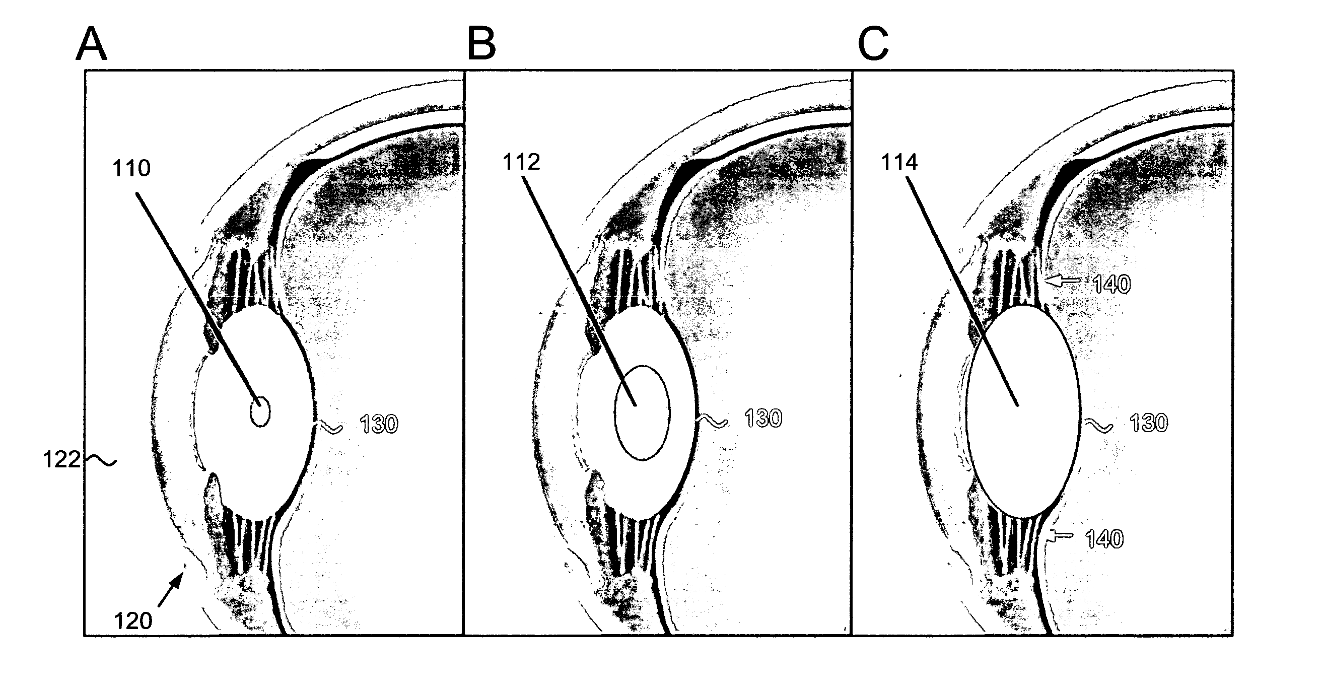
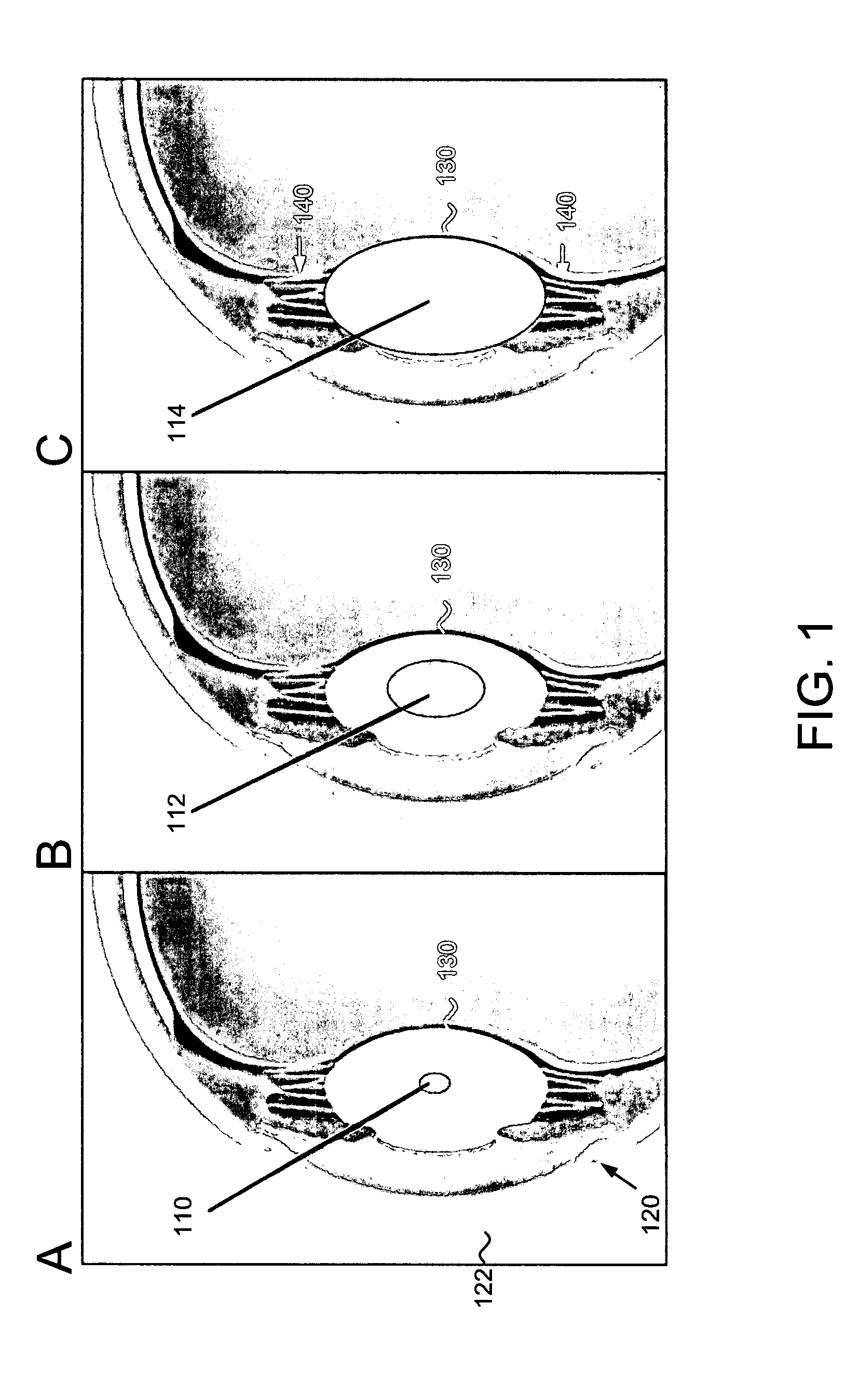
[0017] The present invention provides a hydrogel-based IOL capable of covalently binding to a lens capsule upon implantation into an eye. The hydrogel may be composed of any polymer capable of rapid swelling upon hydration. A schematic of swelling of an IOL on implantation into a lens capsule is shown in FIG. 1. FIG. 1A shows a dehydrated IOL 110 that has been implanted through incision 120 in cornea 122 into lens capsule 130. In FIG. 1B, dehydrated IOL becomes partially hydrated 112 on exposure to the aqueous environment of the lens capsule 130. In FIG. 1C, the IOL is fully swollen 114 within lens capsule 130. Fully swollen IOL 114 can then be controlled by zonules 140 to accommodate the curvature of the lens to different distances.

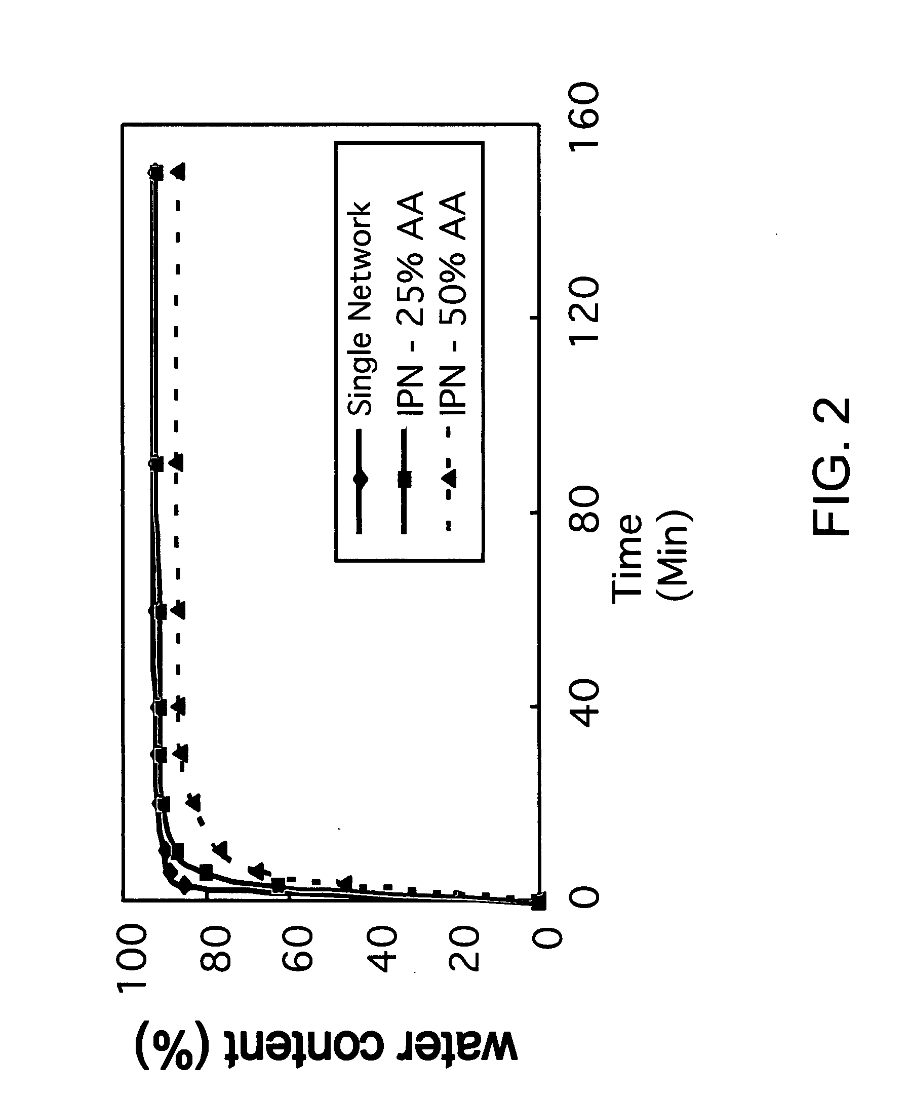
[0018] Preferably, the hydrogel can swell from a dehydrated state to a rehydrated state within about 2 hours. Also preferably, the volume and weight ratios of dehydrated versus rehydrated hydrogel are between about 10:90 (dry:swollen) and about 40:60 (d...


PUM

PropertyMeasurementUnit
water contentaaaaaaaaaa
elastic modulusaaaaaaaaaa

Abstract

The present invention provides a hydrogel-based intraocular lens (IOL) implant that can covalently attach to a lens capsule on implantation into an eye. The inventive IOL has a high refractive index, high elasticity, and is of a similar size to a naturally occurring lens. In addition, the IOL can be implanted in a smaller, dehydrated state, allowing the IOL to be placed in the lens capsule with a small incision (up to about 1 / 10 the volume of the IOL). Exposure to fluid can then initiate rapid swelling of the dried polymer to the shape and dimensions of a natural lens, with full occupation of the lens capsule. Upon equilibrium swelling, the IOL can then make contact with the inner aspect of the lens capsule and covalently bind to it. By this attachment process, the IOL may accommodate in a manner identical to that of the natural lens.

Description

CROSS-REFERENCE TO RELATED APPLICATIONS [0001] This application claims priority from U.S. Provisional Patent Application No. 60 / 783,601, filed Mar. 17, 2006, which is incorporated herein by reference. [0002] This application is a continuation-in-part of U.S. patent application Ser. No. 11 / 243,952, filed Oct. 4, 2005, which claims priority from U.S. Provisional Patent Application No. 60 / 616,262, filed Oct. 5, 2004, and from U.S. Provisional Patent Application No. 60 / 673,172, filed Apr. 20, 2005, all of which are incorporated by reference herein. [0003] This application is also a continuation-in-part of U.S. application Ser. No. 11 / 409,218, filed Apr. 20, 2006, which claims priority from U.S. Provisional Patent Application No. 60 / 673,600, filed Apr. 21, 2005, and which is a continuation-in-part of U.S. patent application Ser. No. 11 / 243,952, filed Oct. 4, 2005, all of which are incorporated by reference herein. [0004] This application is also a continuation-in-part of U.S. patent appl...

Claims


Application Information

Patent Timeline
Patent Type & Authority Applications(United States)
IPC IPC(8): A61F2/16A61K35/44
CPCA61F2/14A61F2/142C12N2533/30C12N5/0621A61L2300/602A61K35/44A61L27/26A61L27/3804A61L27/3813A61L27/3839A61L27/52A61L27/54A61L2300/25A61L2300/252C08L33/08C08L71/02A61L2430/16A61F2/145
Inventor FRANK, CURTIS W.TA, CHRISTOPHERMYUNG, DAVIDNOOLANDI, JAANCARRASCO, MICHAEL R.KOH, WON-GUN
Owner THE BOARD OF TRUSTEES OF THE LELAND STANFORD JUNIOR UNIV
Learn More