Method for manufacturing an energy storage device

a technology of energy storage device and manufacturing method, which is applied in the field of electrochemistry, can solve the problems of degrading the electrochemical properties of the product as a whole, requiring both additional equipment for polymerization and significant time for the process to occur,

Active Publication Date: 2007-10-11
POWERMERS
View PDF25 Cites 7 Cited by
  • Summary
  • Abstract
  • Description
  • Claims
  • Application Information

AI Technical Summary

Benefits of technology

[0025] In satisfaction of these needs and others, the present invention relates to a method of manufacturing an electrochemical energy storage device, such as a hybrid capacitor. In one embodiment, the method includes three steps. The first step is the saturation of a porous electrically conductive material by soaking it in a solution containing an organic solvent and a metal complex able to form a stacked redox polymer, or a mixture of said metal complexes. The concentration of a the complex in a said solution may be no less than 0.0001 mol / L. The porous electrically conductive material may be soaked in a said solution until the porous electrically conductive material saturated with a said metal complex or a mixture of metal complexes is obtained.

Problems solved by technology

The main disadvantage of the traditional method for manufacturing of electrochemical capacitors equipped with positive electrodes modified by redox polymers is the presence of a special stage for the deposition of the polymer onto the porous substrate of the positive electrode prior to the assembly of the capacitor.
This stage requires both additional equipment for polymerization and significant time for the process to occur.
Additionally, during the assembly of the capacitor, in particular, during the arrangement of electrodes in the casing, the polymer layer may be damaged, which may result in the degrading of electrochemical properties of the product as a whole.

Method used


Image

  • Method for manufacturing an energy storage device
  • Method for manufacturing an energy storage device

Examples


Embodiment Construction

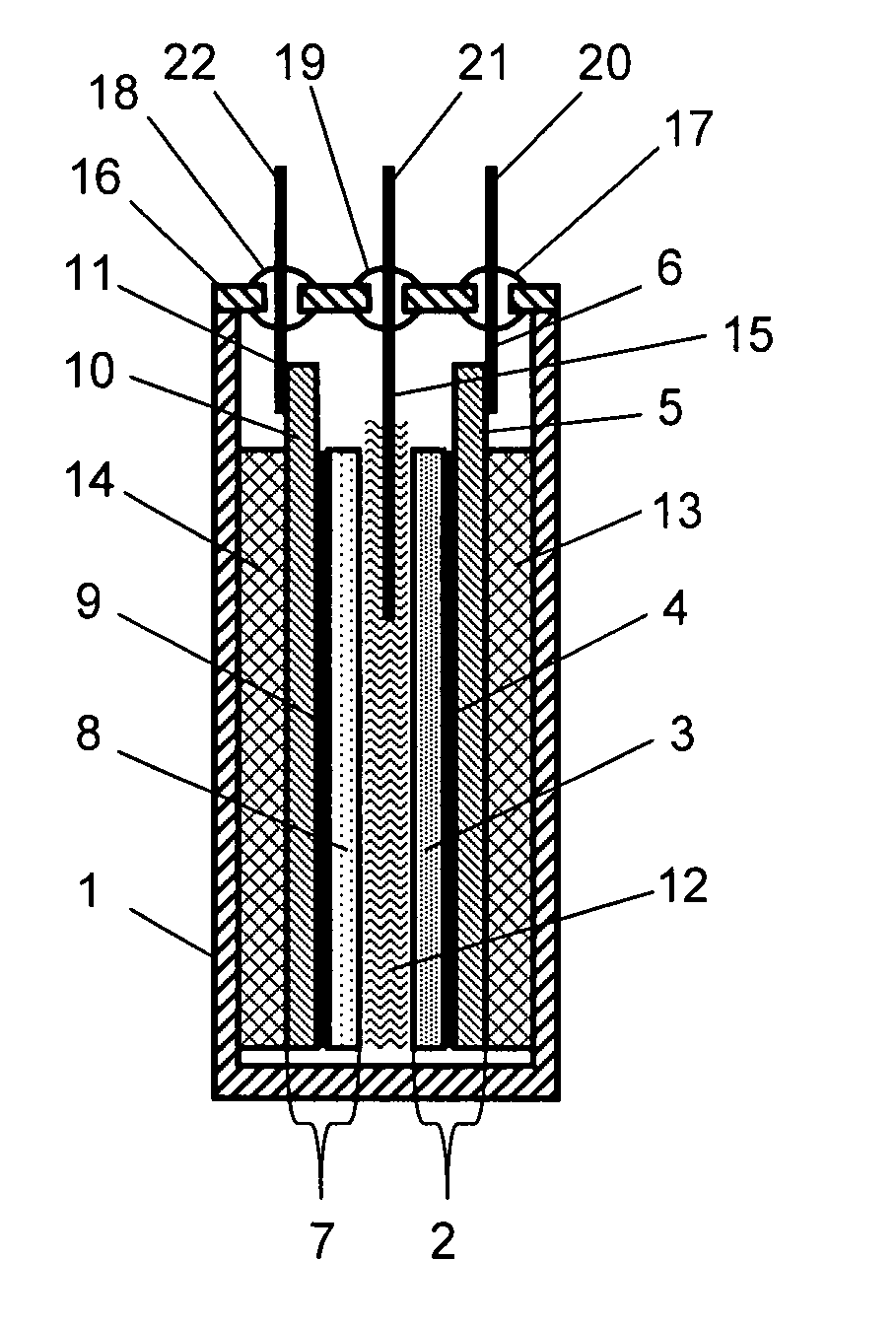
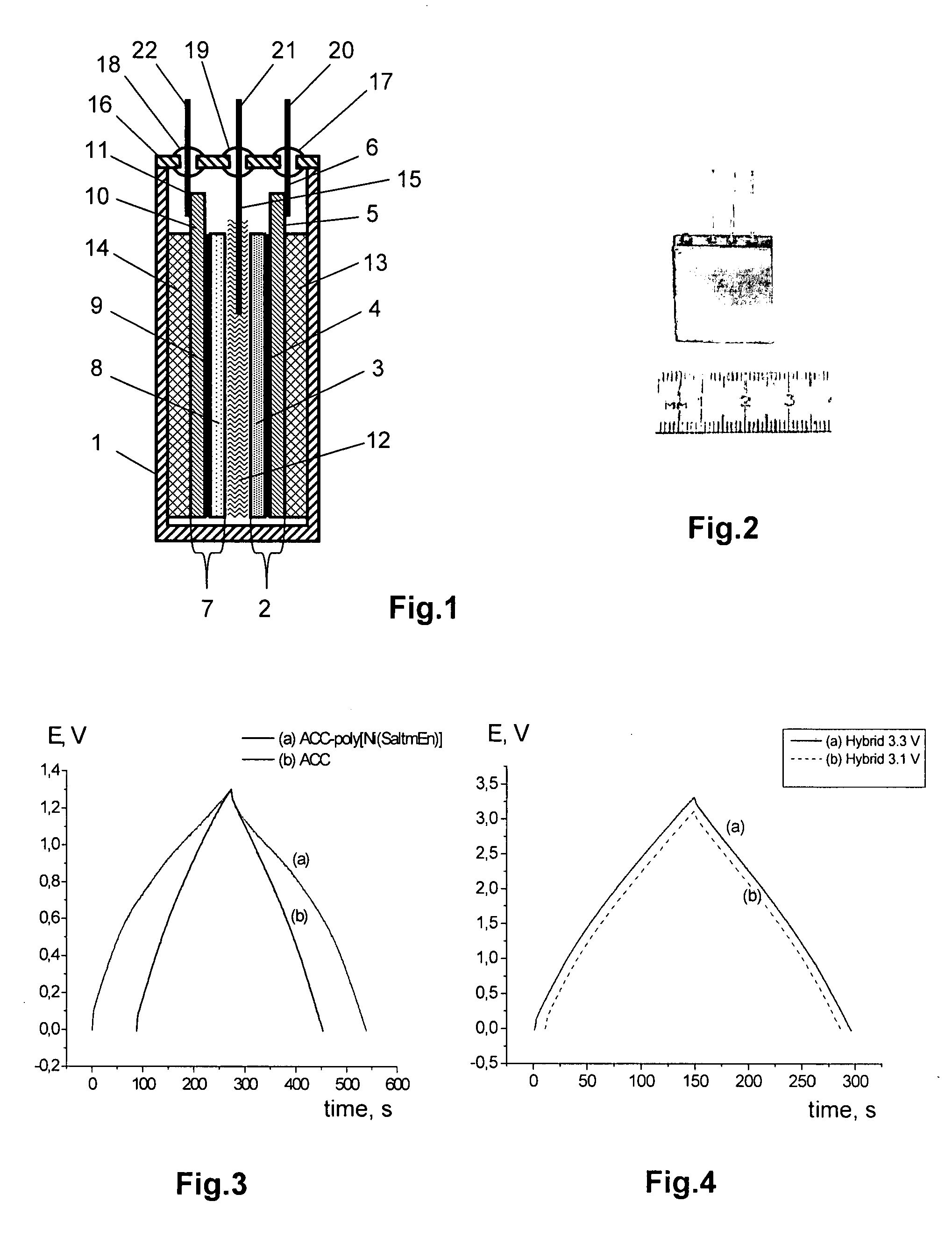
[0048] Aspects of the invention will be more completely understood through the following detailed description, which should be read in conjunction with the attached drawings. In this description, like numbers refer to similar elements within various embodiments of the present invention. Within this detailed description, the claimed invention will be explained with respect to preferred embodiments. However, the skilled artisan will readily appreciate that the methods and systems described herein are merely exemplary and that variations can be made without departing from the spirit and scope of the invention.

[0049] The present invention relates to the development of an improved method for manufacturing a hybrid capacitor by reducing the time required to modify a positive electrode by a polymer, to avoid the use of additional equipment for that polymerization, and to ensure the preservation of the polymer properties during the process of hybrid capacitor manufacturing.

[0050] The pres...


PUM

PropertyMeasurementUnit
temperatureaaaaaaaaaa
current densityaaaaaaaaaa

Abstract

The present invention relates to methods of manufacturing an electrochemical energy storage device, such as a hybrid capacitor. The method comprises saturating a porous electrically conductive material in a solution comprising an organic solvent and a metal complex or a mixture of metal complexes; assembling a capacitor comprising the positive electrode made of porous electrically conductive material saturated with a metal complex, a negative electrode, and a separator in a casing; introducing the electrolyte solution into the casing; sealing the casing; and subsequent charge-discharge cycling of the capacitor. The charge-discharge cycling deposits a layer of an energy-accumulating redox polymer on the positive electrode. The electrolyte solution for filling the hybrid capacitor contains an organic solvent, a metal complex, and substances soluble to a concentration of no less than 0.01 mol/L and containing ions that are electrochemically inactive within the range of potentials between −3.0 V to +1.5 V.

Description

RELATED APPLICATIONS [0001] This application claims priority to U.S. Provisional Patent Application 60 / 785,626 filed on Mar. 24, 2006, the disclosure of which is herein incorporated by reference in its entirety.FIELD OF THE INVENTION [0002] The invention claimed herein relates generally to electrochemistry, more particularly, to methods of manufacturing electrochemical energy storage devices, even more particularly, to methods of manufacturing hybrid capacitors equipped with a positive electrode modified by a redox polymer. BACKGROUND OF THE INVENTION [0003] An electrochemical capacitor, also known as a supercapacitor or an ultracapacitor, is an energy storage device that combines the high energy storage potential of a battery with the high energy transfer rate of a conventional capacitor. The performance characteristics of an electrochemical capacitor can be evaluated in terms of its specific energy, the amount of energy that can be stored per unit weight, and in terms of its speci...

Claims


Application Information

Patent Timeline
Patent Type & Authority Applications(United States)
IPC IPC(8): H01G9/00
CPCH01G9/038H01G9/058H01G9/15H01G9/155Y10T29/417H01G11/24H01G11/26H01G11/58Y02E60/13H01G11/02H01G11/22
Inventor CHEPURNAYA, IRINATIMONOV, ALEXANDERLOGVINOV, SERGEYKOGAN, SAM
Owner POWERMERS
Why Eureka
Try Eureka