
Laser-ultrasonic detection of subsurface defects in processed metals

a technology of subsurface defects and laser ultrasonic detection, which is applied in the field of metal processing and alloys, can solve the problems of metal processing defects that may occur within the processed region of metals, such as voids, pores, disbonds and cracks, and are not practical for in-line us

Inactive Publication Date: 2007-10-11
OPTECH VENTURES
View PDF15 Cites 28 Cited by
  • Summary
  • Abstract
  • Description
  • Claims
  • Application Information

AI Technical Summary

Benefits of technology

Enables 100% parts inspection and real-time process control by detecting subsurface defects in metals processed by various methods, including laser cladding and friction stir processing, allowing for continuous monitoring of each layer during the metal processing operation.

Problems solved by technology

Advanced metal processing typically occurs at high speeds and often involves expensive workpieces and materials so that rapid feedback on the quality of the processed region is critical to controlling scrap rates and costs.
Defects that may occur within processed regions of metals include voids, pores, bondlines (incompletely formed bonds), disbonds and cracks.
Metal processing defects often occur below the surface of the processed region where they cannot be detected by optical, spectroscopic or laser profilometer techniques.
Conventional ultrasonic detection methods are sensitive to such subsurface defects but require that the inspected workpiece be in contact with a fluid, which is not practical for in-line use.
Inspection methods requiring physical contact between the workpiece and a probe are generally impractical for in-line defect detection.
In addition, surface irregularity and roughness typical of processed metal surfaces tend to produce noise signals that interfere with ultrasonic detection based on piezoelectric or EMAT transducers, as well as other conventional methods.
Typical defects in ingots and castings include pores and inclusions.
Typical defects in railway rails include cracks, which need to be detected in-service.
However, bulk ultrasonic waves are not well-suited for detecting near-surface (i.e., subsurface) defects for which the delay time for waves reflected from defects is very short, making ultrasonic measurements difficult.
In addition, application of prior art laser ultrasonic methods has generally been limited to smooth and relatively even surfaces to avoid speckle noise associated with surface roughness and unevenness.
In contrast, metallic surfaces processed by laser cladding, friction stirring or other methods tend to be uneven and relatively rough.
Consequently, prior art laser ultrasonic inspection methods cannot be directly applied to detection of defects in processed metallic workpieces.
The limitations of prior art laser ultrasonic methods are particularly acute for defect detection during laser cladding.
This requires detection of subsurface defects that are very near the top surface, which cannot be accomplished using the bulk ultrasonic waves generally employed in the prior art.
The transducer-based approach described in both of these prior art patents is unsuitable for use on processed metal surfaces, which tend to be relatively rough and uneven, and cannot be used for in-line monitoring during metal processing.
In addition, the Rayleigh wave velocity measurements used by Lindgren are relatively insensitive to metal defects, and do not provide the directional information needed for detection of localized defects.
Likewise, the ultrasonic frequency analysis used by Tittmann does not provide the directional information needed to locate subsurface defects.

Method used


Image

  • Laser-ultrasonic detection of subsurface defects in processed metals
  • Laser-ultrasonic detection of subsurface defects in processed metals
  • Laser-ultrasonic detection of subsurface defects in processed metals

Examples


example 1

[0049]FIG. 4 shows acoustic waveforms illustrating detection according to the invention of a simulated defect (blind hole 1.5 mm diameter and 0.4 mm deep in the back surface) in a machined stainless steel plate (6.4 mm thick). When the detection spot did not overlap the simulated defect, the acoustic waveform exhibited a relatively narrow peak (labeled “no overlap” in FIG. 4) corresponding to arrival of the direct-arriving Rayleigh wave, which was generated at a time of 1 μs in the plot of FIG. 4. When the detection spot did overlap the simulated defect, this peak (labeled “defect overlap” in FIG. 4) was broadened by the signal corresponding to arrival of the scattered acoustic wave at a later time.

example 2

[0050] A B-scan was generated for a machined stainless steel plate (6.4 mm thick) with a simulated defect (blind hole 1.5 mm diameter and 0.4 mm deep in the back surface). The defect was detected at the expected location in the B-scan as a time-delayed bulge in the vertical line corresponding to the direct-arriving Rayleigh wave.

example 3

[0051] A B-scan was generated for a machined titanium alloy 4-6 plate (6.7 mm thick) with a simulated defect (blind hole 1.0 mm diameter and 0.4 mm deep in the back surface). The defect was detected at the expected location in the B-scan as a time-delayed bulge in the vertical line corresponding to the direct-arriving Rayleigh wave. There is less grain scattering in titanium than in steel, so that more ultrasonic features were visible in the titanium plate. In addition to the bulge associated with direct scattering from the simulated defect, the B-scan exhibited two prominent diagonal lines that are associated with surface waves reflected from this defect. These diagonal lines, whose slopes depend on the surface wave velocity, may also be useful for defect detection and localization.


PUM

PropertyMeasurementUnit
wavelengthaaaaaaaaaa
distanceaaaaaaaaaa

Abstract

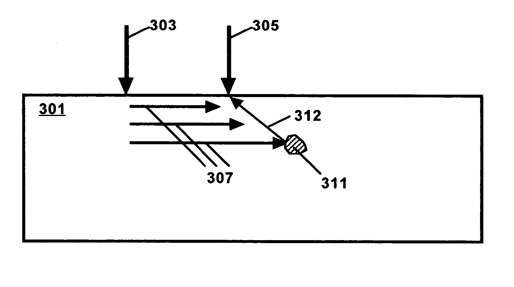
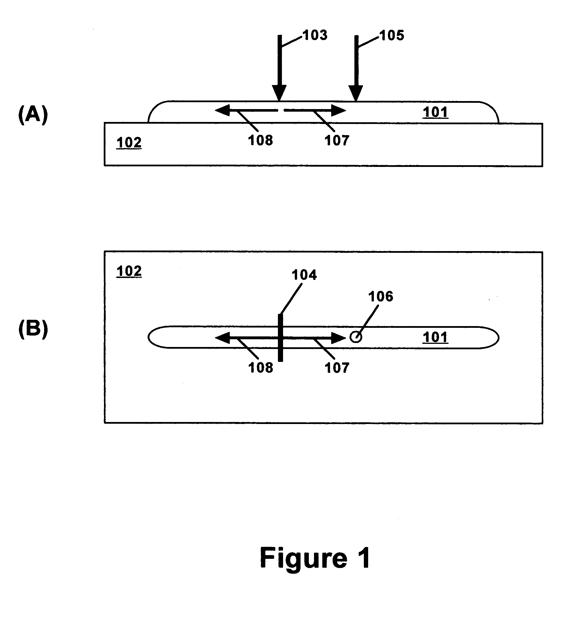
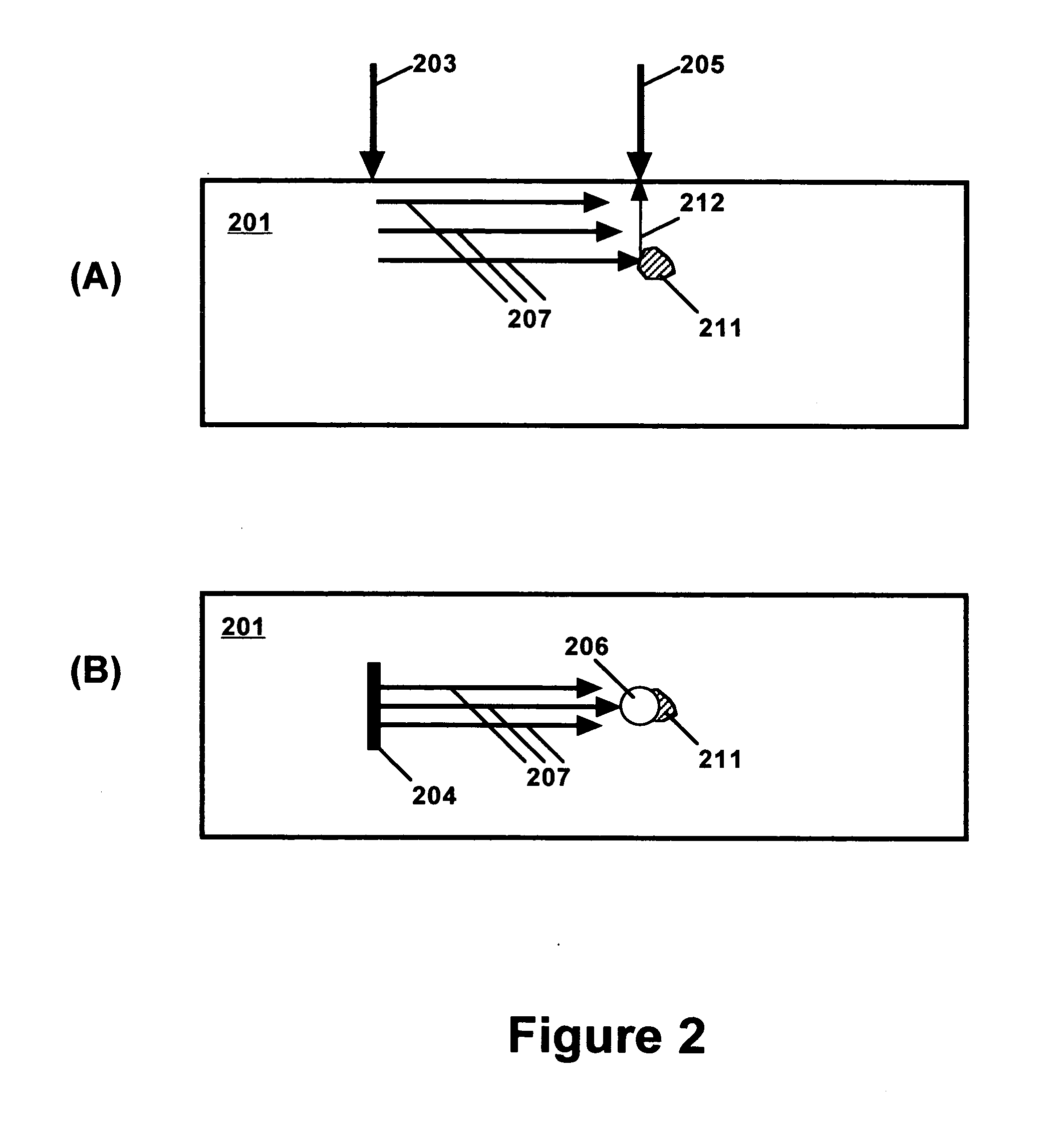
Subsurface defects in a processed metal are detected by a laser-ultrasonic method involving generation of a surface acoustic wave at one location on the processed metal surface, and detection of a scattered acoustic wave at another location on the processed metal surface. The method can be used in-line to provide real time monitoring of laser cladding and other metal processing operations.

Description

U.S. GOVERNMENT RIGHTS [0001] This invention was made with Government support under a contract awarded by the United States Army. The Government has certain rights in this invention.BACKGROUND OF THE INVENTION [0002] 1. Field of the Invention [0003] The present invention is generally related to processing of metals and alloys, and is more specifically concerned with detection of defects generated near the surface of a workpiece during processing. [0004] 2. Description of the Related Art [0005] Advanced metal processing methods are continuously being developed to enable economical manufacture and repair of parts with improved physical properties and often complicated shapes. For example, laser cladding (also called laser powder deposition) is being developed for build-up of stainless steel, titanium and other metals (from metallic powders) to enable near net shape manufacturing and repair of critical parts. Advanced joining methods include laser welding and friction stir welding. The...

Claims


Application Information

Patent Timeline
Patent Type & Authority Applications(United States)
IPC IPC(8): G01N29/04G01N21/88
CPCG01N21/1702G01N29/221G01N29/2418G01N2291/044G01N2291/0422G01N2291/0423G01N2291/0426G01N29/46
Inventor KLEIN, MARVINSIENICKI, TODDEICHENBERGEER, JEROME
Owner OPTECH VENTURES
Learn More