Thermoelectric conversion apparatus

a technology of conversion apparatus and thermal energy, which is applied in the direction of lighting and heating apparatus, electrochemical generators, cell components, etc., can solve the problems of low performance level of thermoelectric devices, large loss, and low performance level of materials, and achieve the effect of highly efficient conversion of thermal energy into electric energy

Inactive Publication Date: 2007-10-11
HONDA MOTOR CO LTD
View PDF14 Cites 22 Cited by
  • Summary
  • Abstract
  • Description
  • Claims
  • Application Information

AI Technical Summary

Benefits of technology

[0008]It is a general object of the present invention to provide a thermoelectric conversion apparatus which does not need t

Problems solved by technology

However, the thermoelectric devices are disadvantageous in that their materials suffer a low performance level.
The problem of the Rankine cycle is that an expander causes a large loss especially for small-scale electric

Method used


Image

  • Thermoelectric conversion apparatus
  • Thermoelectric conversion apparatus
  • Thermoelectric conversion apparatus

Examples


first embodiment

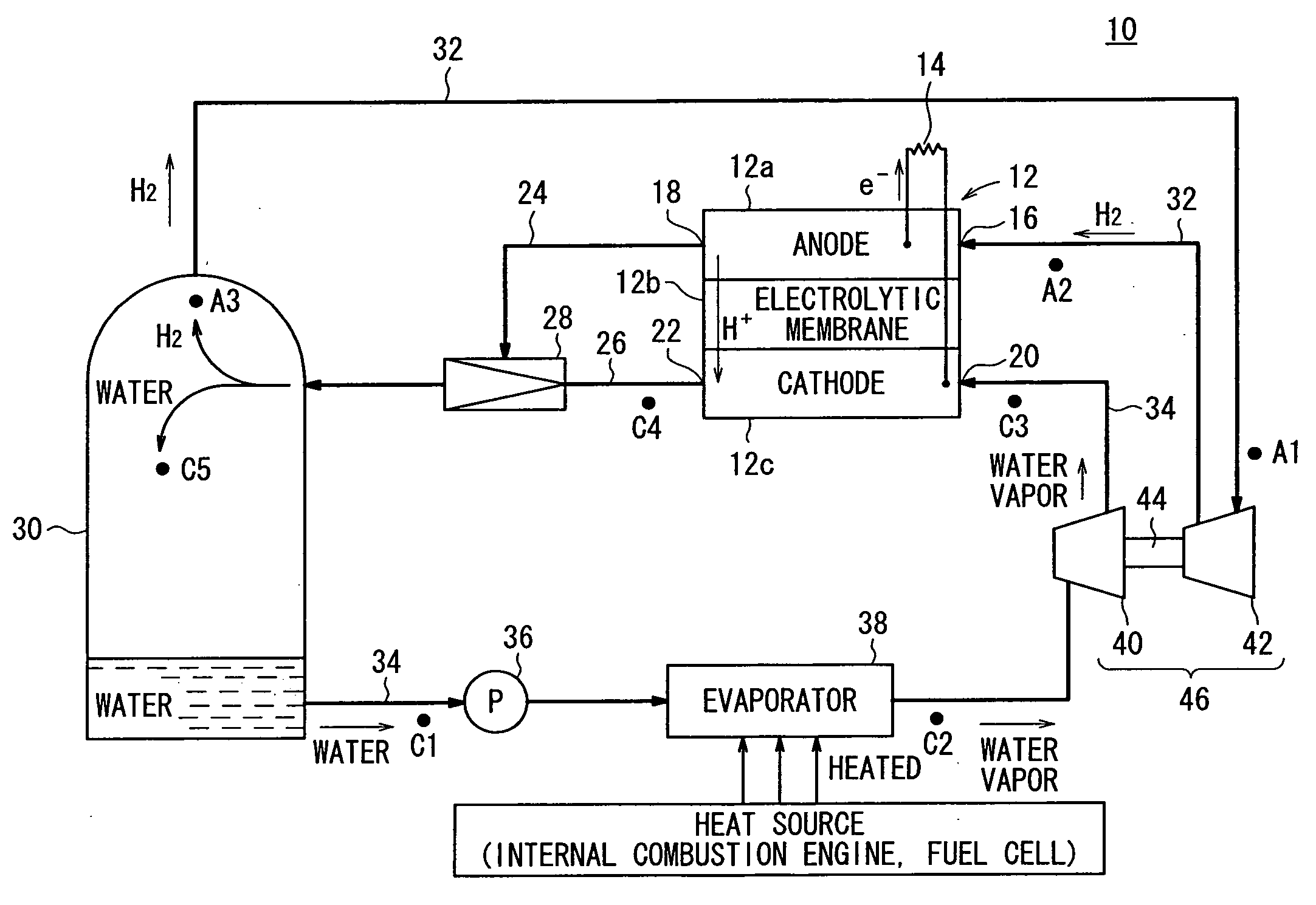
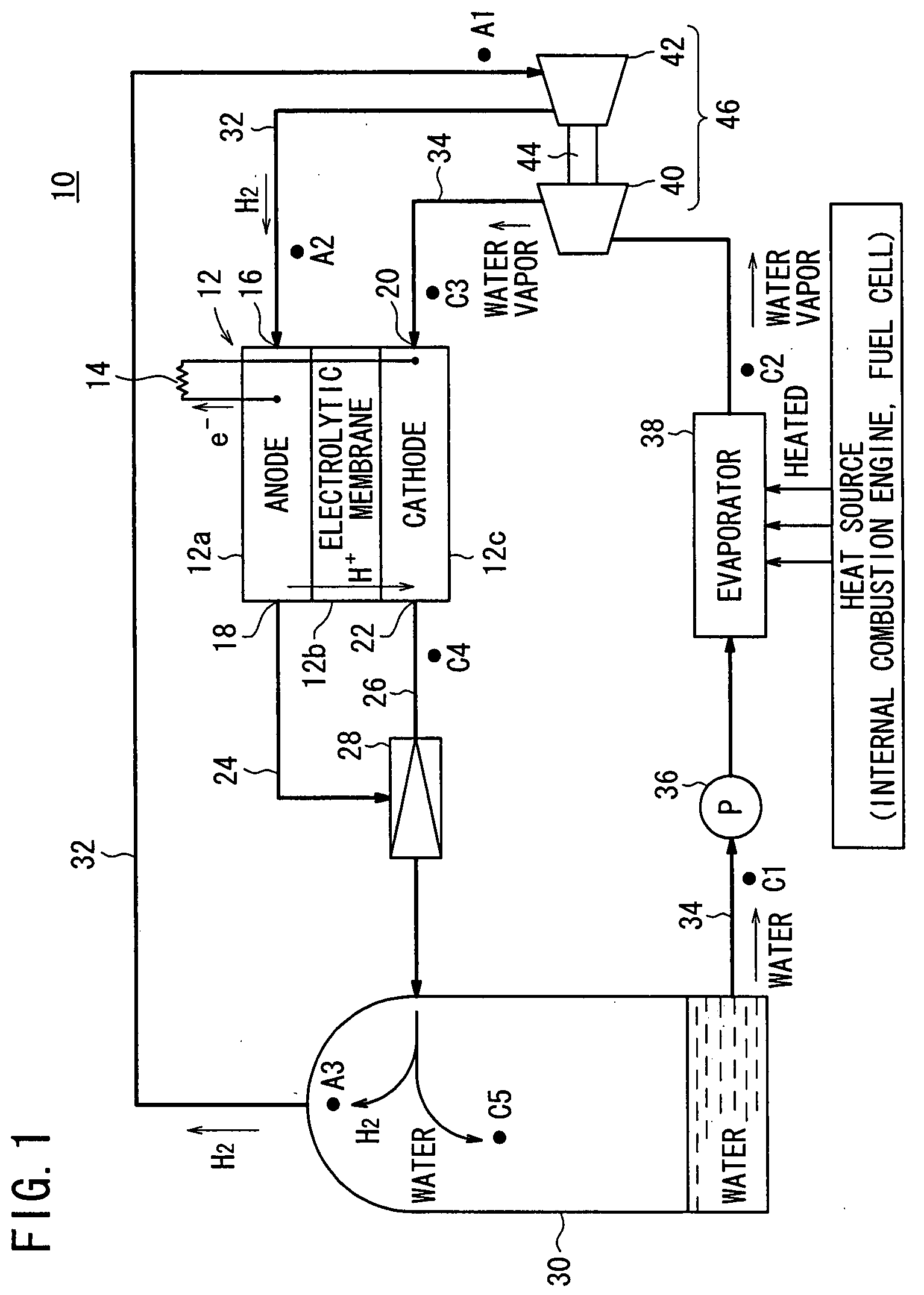
[0020]FIG. 1 schematically shows a thermoelectric conversion apparatus 10 according to the present invention.

[0021]As shown in FIG. 1, the thermoelectric conversion apparatus 10, which is in the form of a closed-cycle system, evaporates a working medium of water into a water vapor with a heat source of waste heat discharged from an internal combustion engine, a fuel cell, or the like (not shown), and supplies the water vapor and a hydrogen gas sealed as a reactive gas in the system to an electric generator 12 to form a concentration cell for electric power generation. The reactive gas may be an oxygen gas or the like rather than a hydrogen gas, and the working medium may be alcohol, ammonia, or the like rather than water.

[0022]The electric generator 12 is of a cell structure comprising an anode electrode 12a, a cathode electrode 12c, and an electrolytic membrane 12b sandwiched between the anode electrode 12a and the cathode electrode 12c. The electric generator 12 is of essentially ...

second embodiment

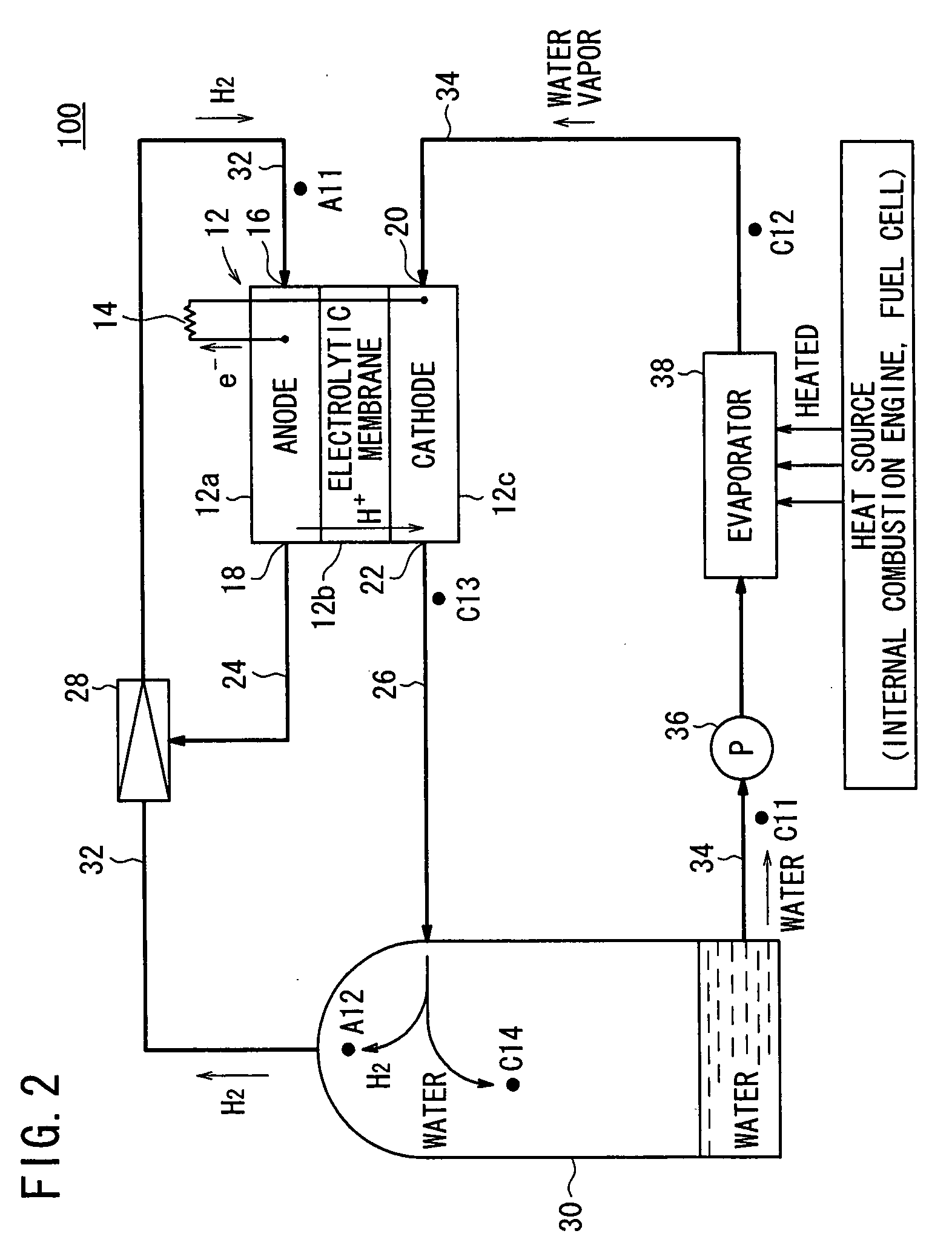
[0052]A thermoelectric conversion apparatus according to the present invention will be described below with reference to FIG. 2. FIG. 2 schematically shows the thermoelectric conversion apparatus, generally denoted by 100. Those parts of the thermoelectric conversion apparatus 100 which are identical to those shown in FIG. 1 are denoted by identical reference characters, and will not be described in detail below.

[0053]The thermoelectric conversion apparatus 100 according to the second embodiment differs from the thermoelectric conversion apparatus 10 according to the first embodiment in that it is free of the hydrogen supercharger 46 and the ejector 28 is connected to the anode supply passage 32, rather than the cathode discharge passage 26.

[0054]In the thermoelectric conversion apparatus 100, when the working medium of water is evaporated into a water vapor by the evaporator 38, the water vapor is directly supplied from the evaporator 38 to the electric generator 12, not via any ex...


PUM


Abstract

A thermoelectric conversion apparatus has an evaporator for heating a working medium in liquid-phase to evaporate the working medium, an electric generator for forming a concentration cell for electric power generation when it is supplied with a reactive gas and the working medium evaporated by the evaporator, and a gas-liquid separator for being supplied with a mixed gas of the working medium and a cathode off-gas discharged from the electric generator and separating the mixed gas into the working medium and the reactive gas. The thermoelectric conversion apparatus also has an anode supply passage for supplying the reactive gas separated by the gas-liquid separator to the electric generator, and a cathode supply passage for supplying the working medium separated by the gas-liquid separator through the evaporator to the electric generator.

Description

BACKGROUND OF THE INVENTION[0001]1. Field of the Invention[0002]The present invention relates to a thermoelectric conversion apparatus for converting thermal energy into electric energy.[0003]2. Description of the Related Art[0004]Using a thermoelectric conversion apparatus for the conversion of waste heat discharged from an internal combustion engine, a fuel cell, etc., for example, into electric energy makes it possible to greatly increase the overall efficiency of a system including such a thermoelectric conversion apparatus.[0005]For example, thermoelectric devices and the Rankine cycle are known for use in thermoelectric conversion processes for converting thermal energy into electric energy. However, the thermoelectric devices are disadvantageous in that their materials suffer a low performance level. The problem of the Rankine cycle is that an expander causes a large loss especially for small-scale electric power generation. Both the thermoelectric devices and the Rankine cyc...

Claims


Application Information

Patent Timeline
IPC IPC(8): C25B9/00H01L35/30
CPCH01M8/04007H01M8/04089H01M8/04097H01M8/04111Y02E60/50H01M8/04201H01M8/04291H01M8/1016H01M2300/0094H01M8/04164
Inventor KAMACHI, ATSUSHIITAMI, SHUNSUKE
Owner HONDA MOTOR CO LTD
Why Eureka
Try Eureka