Analog MEMS with non-linear support

Active Publication Date: 2007-10-11
TEXAS INSTR INC
View PDF4 Cites 6 Cited by
  • Summary
  • Abstract
  • Description
  • Claims
  • Application Information

AI Technical Summary

Benefits of technology

[0021] There are two primary techniques for maximizing the effective yield strength of a disclosed beam support structure: 1) the beam may employ a curved geometry, or 2) the beam may be made of a material that is highly elastic (low modulus). A beam that is curved in a plane normal to the direction of deflection would tend to have sufficient elongation to increase the maximum possible deflection. Likewise, a beam constructed of a highly elastic material would allow greater deflection before failure.
[0022] Replacing linear hinge supports with non-linear beam supports can increase the range of tilt angle deflection available for an analog micromirror device. This technique can reduce

Problems solved by technology

DMDs often suffer stiction due to the contact forces present when the electrode pulls the micromirror into position against the electrode contact surface.
Conventional analog micromirrors face their own problems, however.
The result of the differing nature of the electrostatic force and the linear spring force of the torsion hinge is a phenomenon known as “snap-through.” Once the micromirror has deflected approximately one-third the total separation distance between its neutral position and the electrode, conventional analog micromirrors become unstable as the non-linear elect

Method used


Image

  • Analog MEMS with non-linear support
  • Analog MEMS with non-linear support
  • Analog MEMS with non-linear support

Examples


Example

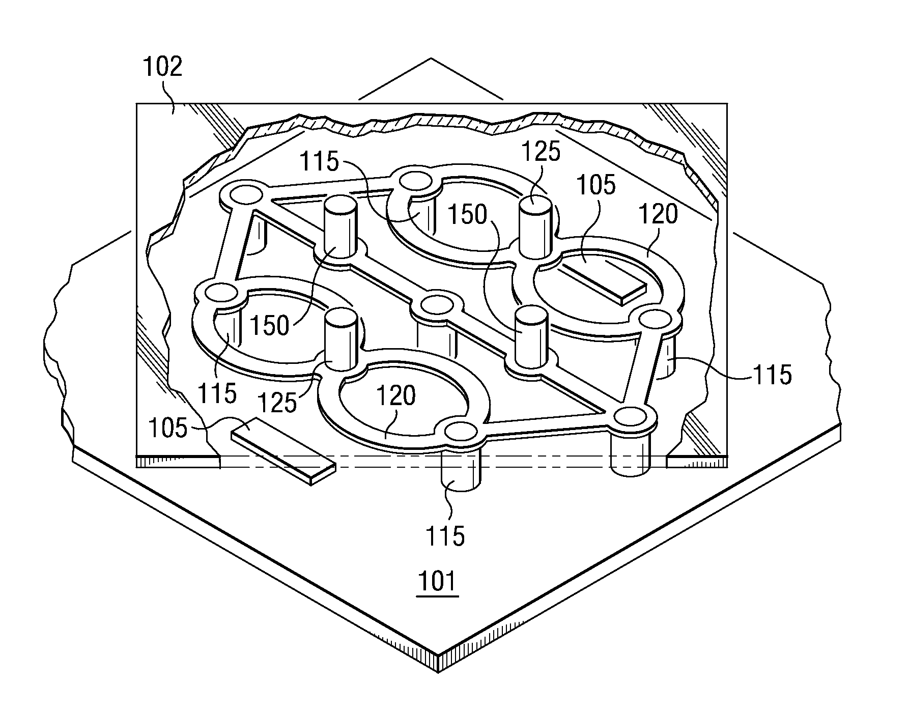
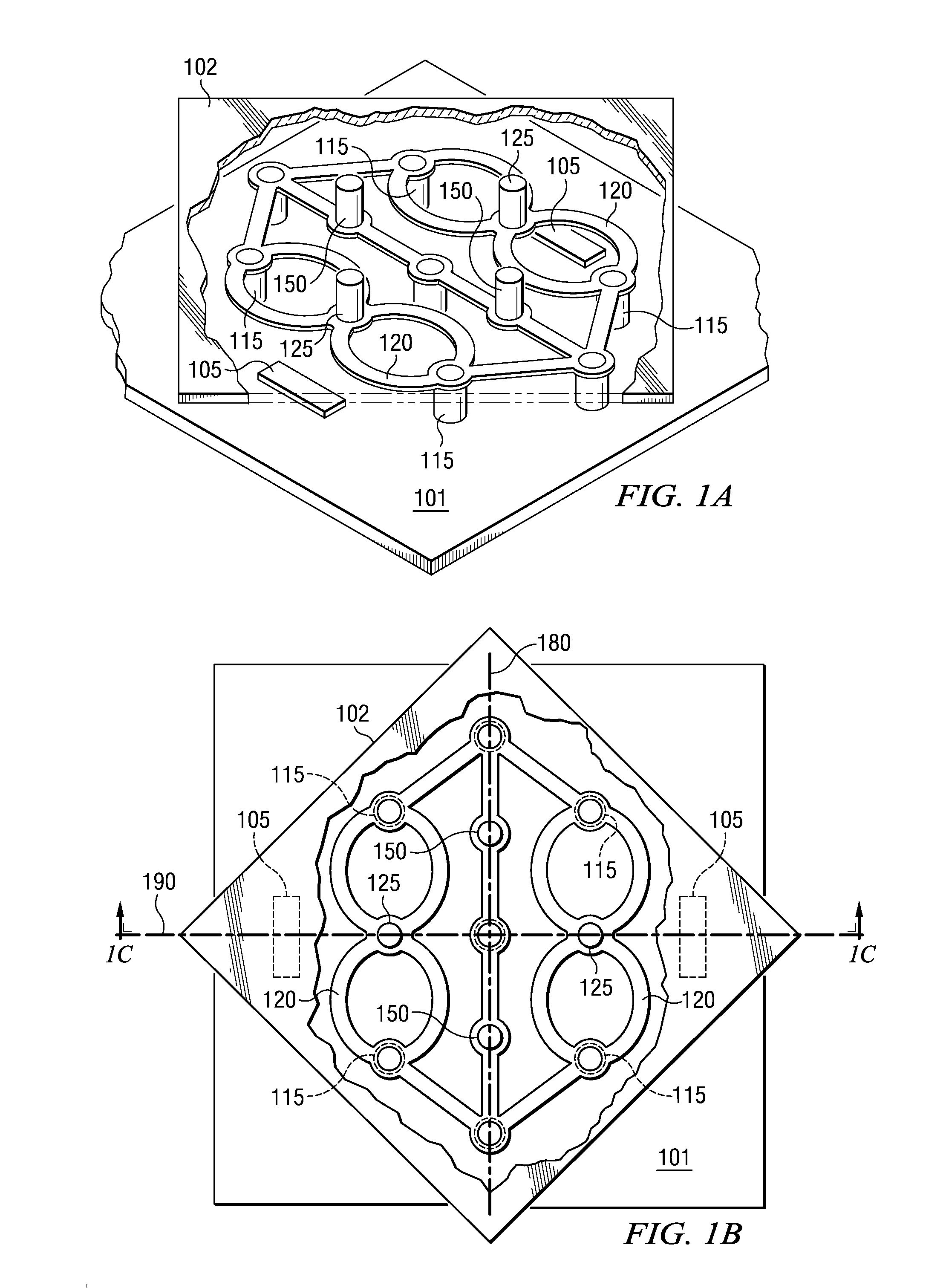
[0032] . 1A illustrates one of the disclosed embodiments for providing non-linear support for an analog micromirror 102. FIGS. 1B and 1C provide additional views of this embodiment, to aid in illustration. The disclosed embodiment has a substrate 101, serving as its base. Electrodes 105 are formed upon the substrate 101, in order to functionally provide an electrostatic attraction force upon a micromirror 102. A micromirror 102 is supported above the substrate 101 in such a way as to be capable of pivoting about a pivot-line axis 180. In the embodiment shown in FIG. 1A, the micromirror 102 is not supported by a torsional hinge; rather it is supported along its neutral pivot-line axis 180 by two pivot supports 150. And in the embodiment of FIG. 1A, one electrode 105 is located on each side of the pivot-line axis 180 of the micromirror 102, typically in a central location spaced between the pivot supports 150 of the micromirror 102, approximately along the center-line axis 190.

[0033]...


PUM


Abstract

The disclosed embodiments reveal an analog MEMS device with a pivotal micromirror that is supported by one or more beams that provide non-linear resistance. An electrode can electrostatically attract the micromirror, while the beam(s) provide resistance to deflection. When the forces equalize, the micromirror is held at a target angle. The beam support disclosed in the embodiments is superior to conventional torsion hinge supports, because it provides non-linear support for the micromirror, better matching the non-linear nature of the electrostatic force.

Description

FIELD OF THE INVENTION [0001] The embodiments described below generally relate to providing non-linear support for micro-electromechanical systems, and more specifically to providing non-linear support for analog micromirrors. BACKGROUND OF THE INVENTION [0002] Recently, the miniaturization of various mechanical devices has sparked a new field of technical advancement. Such micro-electromechanical systems (“MEMS”) integrate mechanical elements with electrical control circuits on a substrate, and are typically manufactured using integrated circuit techniques. Because of their small size, MEMS have become increasingly useful in the development of modern, smart products. Common applications include accelerometers, pressure sensors, actuators, and spatial light modulators. [0003] One type of MEMS device involves micromirrors. Micromirror devices utilize an array of thousands or even millions of tiny, tilting reflective surfaces. These micromirrors can be used to reflect light onto a pro...

Claims


Application Information

Patent Timeline
IPC IPC(8): G02F1/29
CPCG02B26/0841
Inventor MALONE, JOSHUA J.
Owner TEXAS INSTR INC
Why Eureka
Try Eureka