Balancing method for color wheel

a color disc and balancing technology, applied in the direction of rotating bodies, instruments, optical elements, etc., can solve the problems of difficult application of the second balancing plane, achieve the effect of facilitating and improving balancing, increasing the size of the color disc along the rotation axis, and improving the results of rotating color discs

Active Publication Date: 2007-10-11
OERLIKON SURFACE SOLUTIONS AG PFAFFIKON
View PDF9 Cites 15 Cited by
  • Summary
  • Abstract
  • Description
  • Claims
  • Application Information

AI Technical Summary

Benefits of technology

[0011] As mentioned before typically color discs are described as rotating discs. However, since every realistic rotator has a finite thickness even a very thin disc can be expressed as a series of two or more disc shaped rotors. Connecting the centers of masses of each of these discs leads to the center of mass line. In the case of the typical color disc this center of mass line is, compared to the radial dimensions of the wheel, quite small and single plane balancing seems to be the adequate balancing methods. Nevertheless, as the inventors surprisingly found, dual plane balancing, as typically used only for thick rotators, exhibits improved results for rotating color discs. Therefore the inventive wheel according to the present invention comprises balancing means at a first plane which is perpendicular to the rotation axis and in addition balancing means at a second plane which is spaced apart from the first plane and which is as well perpendicular to the rotation axis. Color wheels according to the present invention comprise therefore dual and or multiple plane balancing features. Such features could be for example adding or removal of material.
[0012] When the inventors tried to apply this d

Problems solved by technology

When the inventors tried to apply this dual balancing plane approach, they found that it is quite difficult to apply the second balancing plane.
They finally realized that the origin of the difficulties is the fact that, due to geometrical r

Method used


Image

  • Balancing method for color wheel
  • Balancing method for color wheel
  • Balancing method for color wheel

Examples


Embodiment Construction

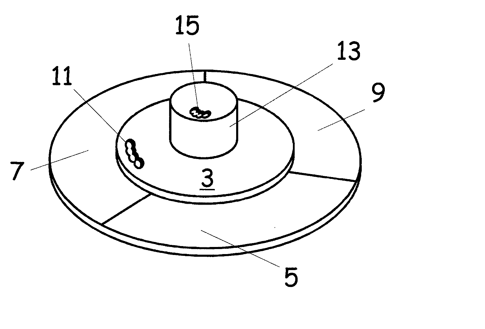
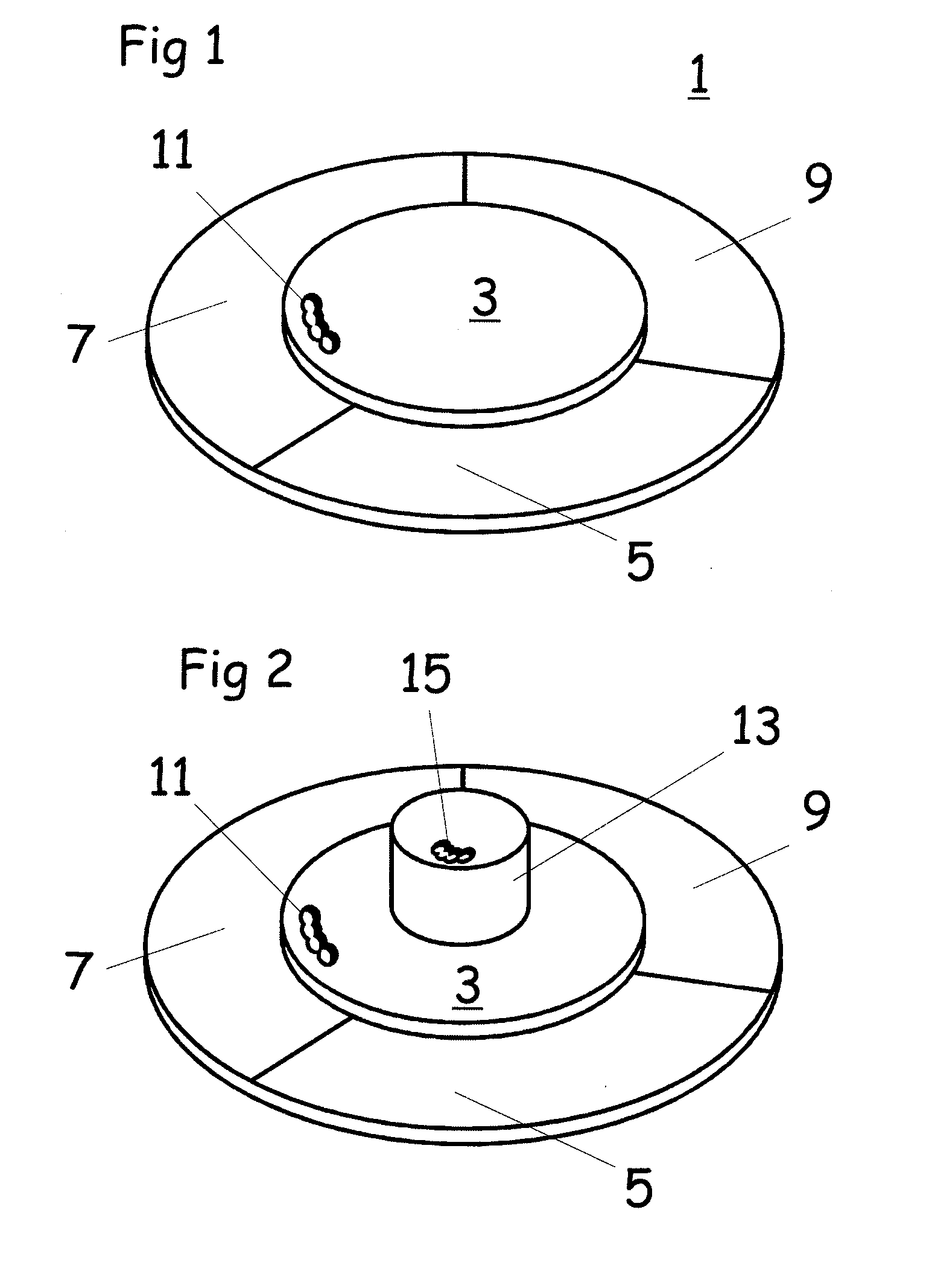
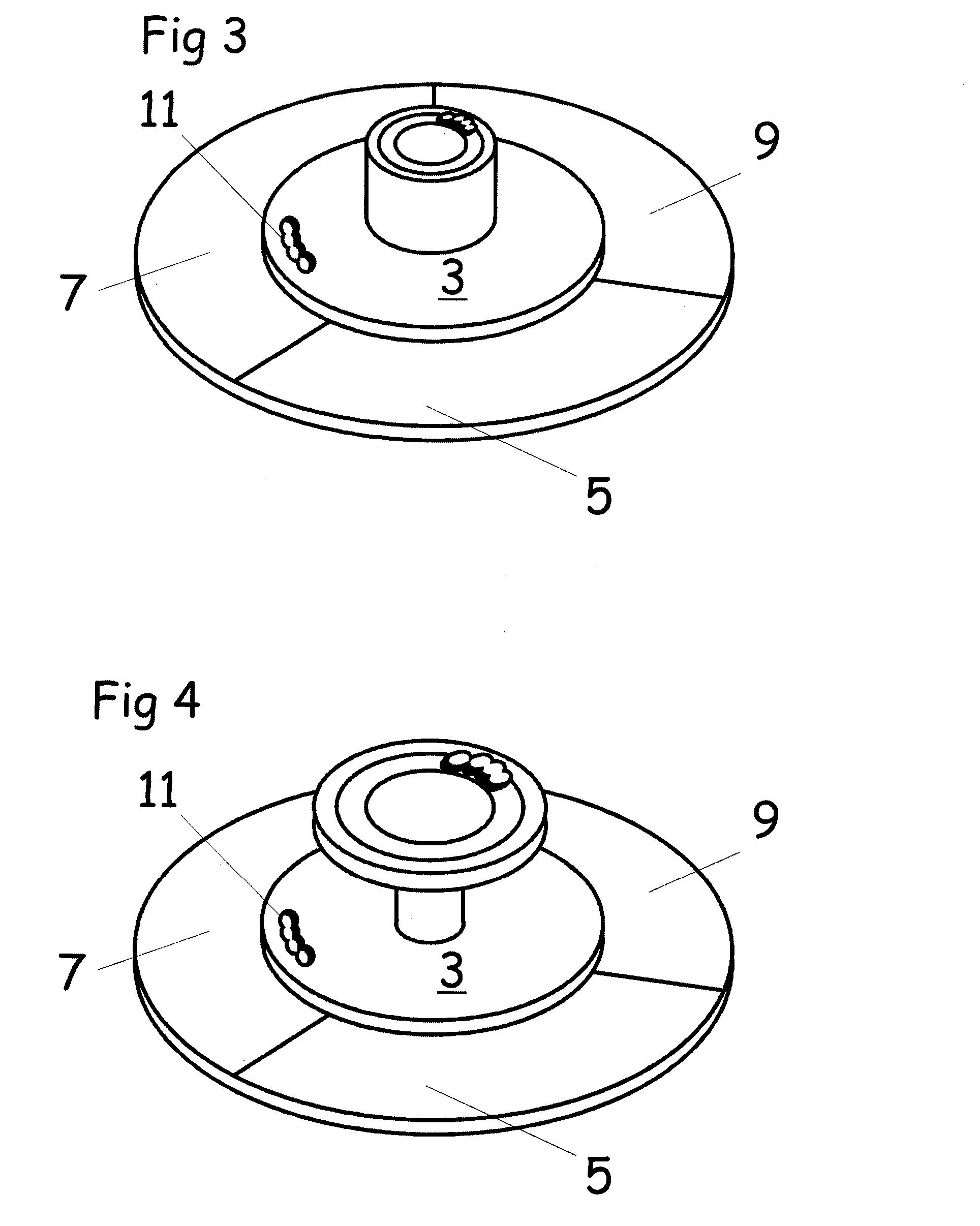
[0020] In the following the invention is described with the help of the figures in more detail. Several preferred embodiments are discussed. However in the next section a typical prior art solution will be described first in order to specifically point out the advantages of the present invention over prior art. The first figure show schematically a color disc 1 according to prior art. Shown is a disc shaped carrier 3 and three color filter segments 5, 7 and 9. In the disc shaped carrier 3 there is a material removal section 1 where material is removed in order to balance the wheel on only a first plane.

[0021] In order to balance the color wheel, it is clamped in the fixture of a balance machine and spun up to 9000 rpm. The balance machine detects the forces created by the rotating unbalanced color wheel and based on that, with the help of algorithms, calculates the required mass and angle of the material to be added or removed to balance the color wheel The balance machine is there...


PUM


Abstract

The invention relates to a color wheel for use in the illumination system of a projector. The color wheel according to the present invention comprises a rotor and a motor for rotating the rotor, the rotor comprising a ring shaped translucent area formed by color filter segments, the translucent area being adapted to continuously extend into a light path as the rotor is rotated, the rotor in a first plane perpendicular to the axis of rotation further comprising first means for balancing, the rotor in a second plane perpendicular to the axis of rotation further comprising second means for balancing, wherein first and second plane are spaced apart. Due to the dual plane balancing means the color wheel is better balanced.

Description

FIELD [0001] This disclosure relates to a rotatable color wheel for use in projector systems to enable color sequential illumination of an image panel BACKGROUND [0002] Most of the image projection apparatus for producing colored images on a screen only comprise one image panel: In order to form a colored image the panel needs to be sequentially illuminated with light beams of different colors. If the sequence is displayed fast enough the human eye is not able to timely resolve the resulting color image sequence and results in the impression of a colored image. One method to realize the required sequential illumination is to place into the illumination path dichroic filter segments secured on a rotatable disc shaped carrier. This forms a color disc which is typically connected to a motor. The assembly of such a color disc and the motor is called color wheel. Since the rotation of such a color disc needs to be quite fast, balancing of such a color disc becomes an issue. [0003] In a f...

Claims


Application Information

Patent Timeline
IPC IPC(8): G02B5/22
CPCF16F15/32G01M1/34H02K15/165G02B26/023H02K7/04G02B26/008G01M1/36G01M1/00G02B27/00
Inventor AUELL, ADAMMOSS, WILLCUNNINGHAM, NICK
Owner OERLIKON SURFACE SOLUTIONS AG PFAFFIKON
Why Eureka
Try Eureka