
Self-Routed Layer 4 Packet Network System and Method

a packet network and self-routed technology, applied in the field of data networks, can solve the problems of inability to take into account dynamic parameters, inaccurate or erroneous decisions, and slow routing process, and achieve the effects of simple and inexpensive implementation, increased performance of such a network, and high speed

Inactive Publication Date: 2007-10-11
WOOD SAMUEL F
View PDF14 Cites 19 Cited by
  • Summary
  • Abstract
  • Description
  • Claims
  • Application Information

AI Technical Summary

Benefits of technology

[0033]If the calling party is the talker and the called party is the listener, a simple broadcast network employing one talker and many listeners would be suitable. This type of network quickly breaks down as the number of talkers increases. One approach is to increase the performance of such a network by using a distributed hardware based design that can run at a high speed as opposed to a centralized software based design found in today's networks. As the hardware approach was simple and inexpensive to implement it was chosen for the embodiment.
[0034]Although the broadcast approach works fine on local area networks (LANS), it breaks down when applied to a mesh network because loops can be created with resultant network overload. Broadcasting in mesh networks is sometimes called “flooding.” Techniques such as the spanning tree algorithm can be used to correct this problem but fall short as they are too slow to adapt to changing network conditions. In addition spanning tree can deactivate links needed for load sharing.
[0035]The problem of loops can be eliminated by simply destroying all duplicate broadcast packets, this technique is sometimes called quenching. This embodiment caches and forward the first instance of each broadcast packet to arrive at a node and destroys all future instances. These packets are called hunting packets in the embodiment.
[0039]This embodiment uses a method called bridging to reduce the transmission of unnecessary hunting packets. When a hunting packet from a first node looking for a second node arrives at any given node the identity of the first node is cached at the receiving port. Any future hunting packets looking for the first node, including those from the second node, will only be forwarded on ports bearing the signature of the first node. This technique along with others known to those of skill in the art limits the number of hunting packets to a manageable level.
[0041]Special hardware is disclosed in the embodiment that allows the checking to be done in a pipelined fashion so that no appreciable delay is incurred as the hunting packet passes through each node.
[0057]10) Provisioning used to enhance network performance, but not required for basic setup.

Problems solved by technology

These protocols were not able to take into account dynamic parameters such as congestion, policy or QOS.
In real time the routing process can be slow compared to the dynamic changes in the network metrics causing inaccurate or erroneous decisions to be made.
Managing the flow of information through the network can be difficult and expensive.4.)
Paths routed in this manner are not verified so may not be reliable.5.)
Real time routing decisions cannot be made in this way as delays are too long to be practical for a computer network.7.)
As the network grows more complex it becomes more difficult to make these routing decisions.

Method used


Image

  • Self-Routed Layer 4 Packet Network System and Method
  • Self-Routed Layer 4 Packet Network System and Method
  • Self-Routed Layer 4 Packet Network System and Method

Examples


Embodiment Construction

Physical Architecture

[0087]This section describes the physical architecture of a model system design of an MPLS type network using the SRP Networking methods.

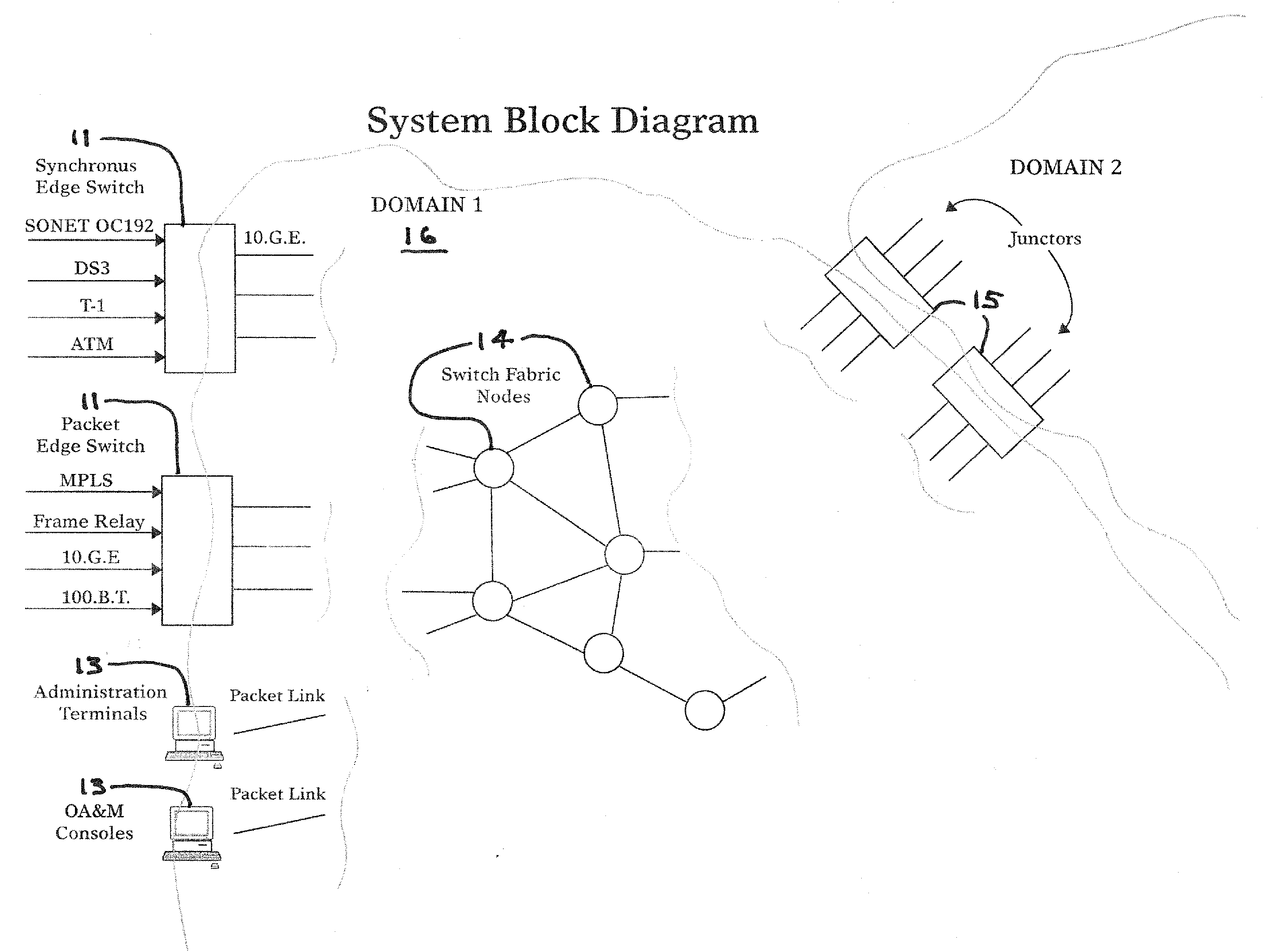
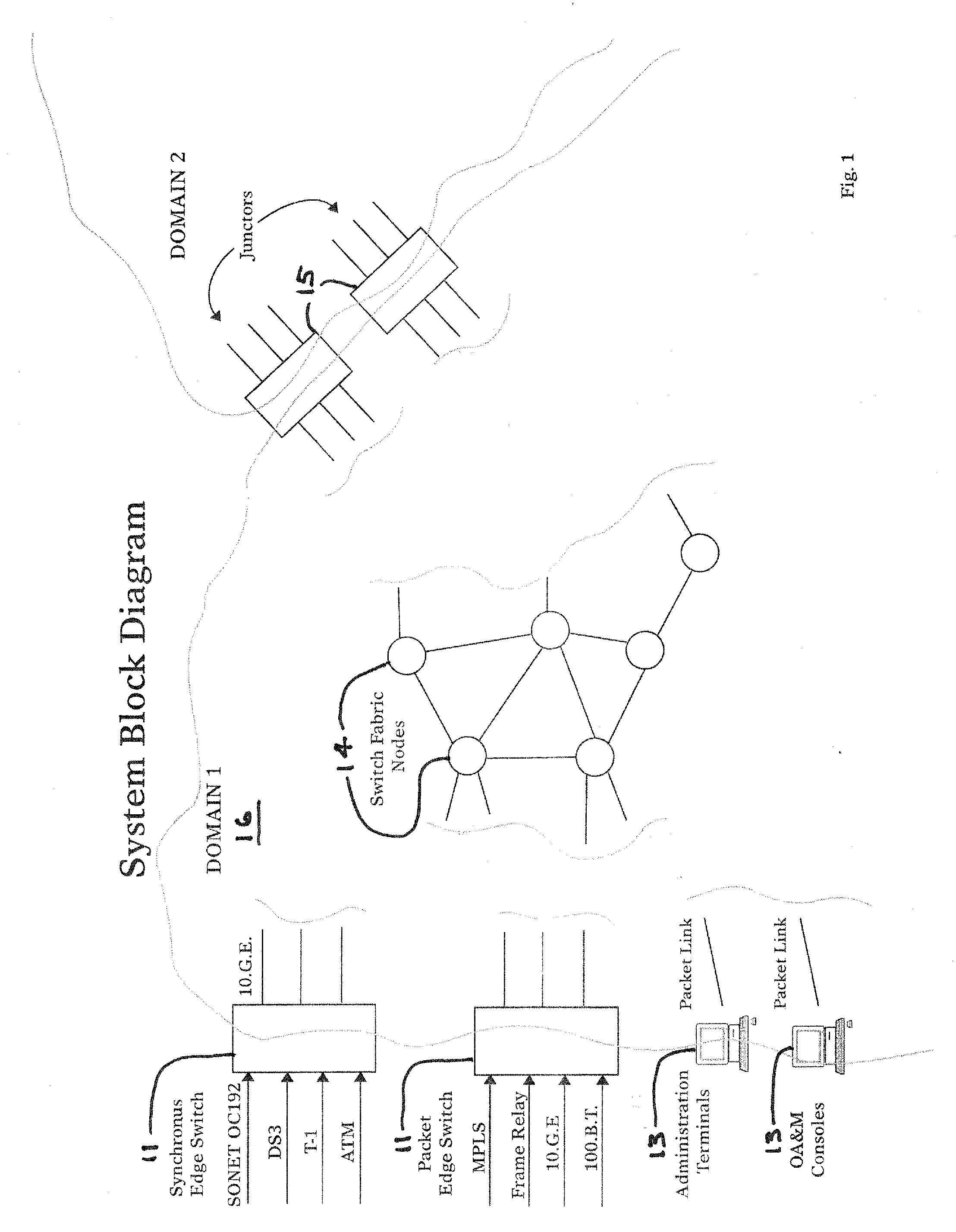
[0088]A domain is a collection of nodes that are managed by the same entity or are in a specific geographic area. FIG. 1 shows a typical SRP Network Domain. A domain 16 consists of Edge Nodes 11, Junctors 15, Switch Fabric Nodes 14, OA&M consoles 13 and Links that interconnect the nodes.

[0089]Edge nodes 11 provide entrance and exit ports for a SRP Networks Domain. Edge Nodes 11 translate between the layer 4 SRP Networks Architecture and other networking architectures such as MPLS, ATM, Frame Relay, SONET, TCP-IP, TDM, etc. Edge Nodes 11 use Hunting Packets to build Label Switch Paths (LSPs) to other Edge Nodes subject to QOS requirements such as latency and guaranteed bandwidth, and subject to policy constraints such as access restrictions, use of specific service providers, link cost or types of links. An Edge node can be a sp...


PUM


Abstract

The embodiment discloses a connection oriented packet network using an MPLS-type label switching technology. The network uses a very fast hardware-oriented self-routing protocol that can expose a path right-of-way and program a connection between a calling and called party at wire speed. The embodiment requires no provisioning and is well suited for mobile and ad-hoc networks. The system and method taught can be applied to other data networks where performance guarantees are important.

Description

CROSS REFERENCE TO RELATED APPLICATIONS[0001]This application claims the benefit of U.S. Provisional Application No. 60 / 790,430, filed Apr. 6, 2006, which is incorporated herein by reference.FIELD OF THE INVENTION[0002]The field of this invention is data networks using label switching such as MPLS. However, the methods taught here can be applied to other data networks including ad-hoc, mobile, and traditional packet networks, cell or frame-switched networks, time-slot networks and the like.BACKGROUND OF THE INVENTION[0003]Open Systems Interconnection (OSI) layers are known to those of skill in the art as a series of protocol layers to define communications in data networks. The first layer relates to the physical aspects of communication. Examples are T-1 and 100-base T. The second layer is called the data link layer. This layer is used to format data passing over a given link. Examples include Ethernet and HDLC. Layer 3 is called the network layer. This layer supports end-to-end pa...

Claims


Application Information

Patent Timeline
Patent Type & Authority Applications(United States)
IPC IPC(8): H04L12/56
CPCH04L45/50H04L45/04
Inventor WOOD, SAMUEL F.
Owner WOOD SAMUEL F
Learn More