PON system

a technology of optical network and pon, applied in the field of pon system, can solve problems such as congestion, and achieve the effect of surplus bandwidth

Inactive Publication Date: 2007-10-11
HITACHI LTD
View PDF7 Cites 48 Cited by
  • Summary
  • Abstract
  • Description
  • Claims
  • Application Information

AI Technical Summary

Benefits of technology

[0024]According to the present invention, when congestion occurs at a specific output port of a GW to which an OLT is connected as shown in FIG. 20, the OLT can delete the bandwidth of the specific ONU that is transmitting communication frames to the congestion occurred output port selectively, thereby the OLT can distribute a surplus bandwidth in the PON section generated due to the deletion to other ONUs. Thus the GW congestion state can be eliminated without lowering the whole system throughput.

Problems solved by technology

If such a logic path is set, however, congestion might occur in a gateway (GW) in which logic paths handling much data respectively are concentrated as shown in FIG. 19 and some frames to be transferred might be discarded in the worst case.
That has been a problem.

Method used


Image

  • PON system
  • PON system
  • PON system

Examples


first embodiment

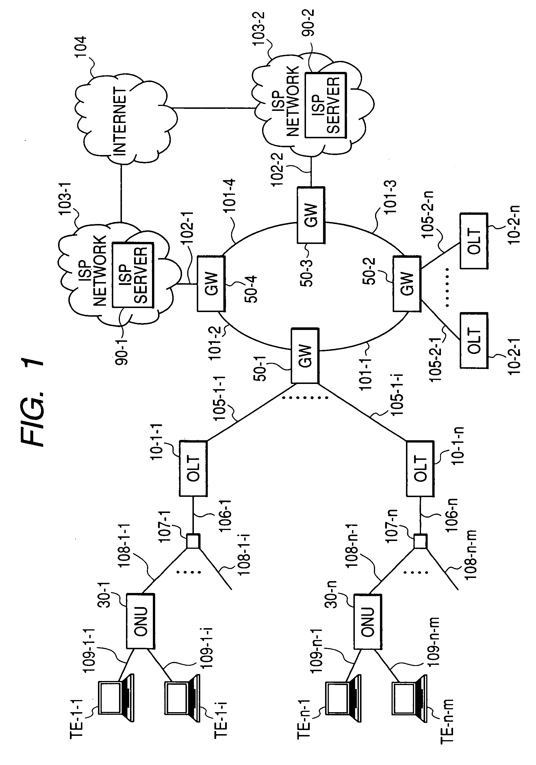
[0046]FIG. 1 is a diagram for showing an example of a communication network to which the present invention applies.

[0047]A carrier network consists of an access network and a metro network. The access network includes optical line terminals (OLT) 10 (10-1-1 to 10-2-n) and plural optical network units (ONU) 30 (30-1 to 30-n) connected to each other through a passive optical network (PON) respectively. The metro network includes plural gateways (GW) 50 (50-1 to 50-4) connected to each other through lines 101 (101-1 to 101-4).

[0048]Each of subscriber terminals TE (TE-1-1 to TE-n-m) is connected to the ONU 30 through one of the lines 109 (109-1 to 109-n-m) and connected to the metro network through a PON and an OLT 10. The gateways GW 50 of the metro network are divided into two types; GWs like 50-1 and 50-2 connected to an OLT 10 through the lines 105 (105-1-1 to 105-2-n) and GWs like 50-3 and 50-4 connected to ISP networks 103 (103-1 and 103-2) through the lines 102 (102-1 and 102-2)....

second embodiment

[0140]FIG. 17 is another embodiment of the network to which the present invention applies.

[0141]In this embodiment, GWs 500-1 and 500-2 of a carrier network are provided with a line interface (PON interface) having OLT functions respectively and houses PON optical fibers 106 (106-1-1 to 106-2-n) directly.

[0142]FIG. 18 is a configuration of the GW 500-1.

[0143]The GW 500-1 consists of plural network interface parts 510 (510-1 to 510-q), a frame relay part 52 for connecting those interface parts 510 to each other, a GW management part 53, and a management information table 54. The network interface part 51-1 for housing the PON optical fiber 106 is provided with a PON interface (IF) 5110 instead of the Ethernet IF 511 shown in FIG. 8. The network interface part for housing the carrier network lines 101 (101-1 and 101-2) is provided with an Ethernet IF 511 shown in FIG. 8.

[0144]The PON interface (IF) 5110 is the same as that of the OLT 10 shown in FIG. 4 except for that the Ethernet IF ...


PUM


Abstract

Disclosed herewith is a PON system and a bandwidth controlling method capable of controlling congestion with use of an upstream bandwidth in a PON section efficiently when congestion occurs in a gateway (GW) connected to an OLT. An OLT connected to a plurality of ONUs through a passive optical network (PON) and to a gateway (GW) through a communication line, when receiving a congestion occurrence notice indicating a congestion occurred output number from a GW, identifies the identifier of the ONU that is using a GW output line having the congestion output port number and shifts the bandwidth controlling of the PON section in a normal mode for allocating a bandwidth to each ONU normally to that in a bandwidth suppression mode for allocating a congestion time allowable bandwidth that is less than the current bandwidth to the ONU having the identified ONU identifier and a bandwidth to each of other ONUs according to its transmission queue length.

Description

CLAIM OF PRIORITY[0001]The present application claims priority from Japanese application JP 2006-107790 filed on Apr. 10, 2006, the content of which is hereby incorporated by reference into this application.FIELD OF THE INVENTION[0002]The present invention relates to a passive optical network (PON) system comprising an optical line terminal (OLT) and plural optical network units (ONUs) connected to each other through a passive optical network (PON), more particularly to a method for controlling the bandwidth of a PON section when line congestion occurs in any of the output ports of a frame transfer device connected to the OLT.BACKGROUND OF THE INVENTION[0003]A carrier network for providing services of connection to the Internet consists of an access network for holding a plurality of subscribers directly and a relay network (hereunder, to be referred to as a metro network) for bundling a plurality of access networks. And a passive optical network (PON) is one of such access network ...

Claims


Application Information

Patent Timeline
Patent Type & Authority Applications(United States)
IPC IPC(8): H04J3/22H04B10/27H04B10/272H04B10/275H04L12/44
CPCH04L47/115H04L47/263H04Q2011/0064H04Q11/0071H04Q11/0067
Inventor ENDO, HIDEKIMIZUTANI, MASAHIKOTAKASE, MASAYUKISAKAMOTO, KENICHIASHI, YOSHIHIROKANNO, TAKAYUKIYAMAMOTO, NOBUYUKI
Owner HITACHI LTD
Why Eureka
Try Eureka