Microfluidic and nanofluidic electronic devices for detecting changes in capacitance of fluids and methods of using

a technology of electrical devices and fluids, applied in the field of microfluidic and nanofluidic electrical devices, can solve the problems of limiting the general application of sensors to such probes, laborious sequencing of dna, and difficulty in realizing such probes, and achieves the effects of simple, fast, and less expensiv

Inactive Publication Date: 2007-10-11
THE TRUSTEES FOR PRINCETON UNIV
View PDF0 Cites 103 Cited by
  • Summary
  • Abstract
  • Description
  • Claims
  • Application Information

AI Technical Summary

Benefits of technology

[0021] The present invention relates to microfluidic device in which characteristics of a biological cell are determined by applying an electrical signal to an individual cell and detecting signals resulting from the application of the electrical signal. The cell can be passed through a channel from a fluid input apparatus. The channel passes the cell in the vicinity of a pair of electrodes. The width of the channel, rate of flow of fluid containing the biological cell and concentration of the cells in the fluid are selected to allow cells to flow one-by-one in the vicinity of the electrodes. The microfluidic device can be used to determine the DNA content of the cell, to analyze cell-cycle kinetics of populations of the cells and as an assay for abnormal changes in DNA content of cells. The present invention is also referred to as “Capacitance cytometry”, and it has the potential to be simpler, faster, and less expensive than standard laser flow cytometry.

Problems solved by technology

However, the realization of such a probe is extremely challenging given that the necessary technologies for single-molecule detection, isolation, and identification are just emerging and given that the fabrication technology needed to access the length scales compatible with single biomolecules (˜10 nm) is still very much in development.
While each of these has proved successful in specific applications, a number of limitations, including photobleaching and photodamage, restrict their general application to sensors.
For example, sequencing of DNA currently is a labor intensive process which involves cloning, chemical or enzymatic manipulation, and sample analysis on capillary or vertical gels.
While the process of DNA sequencing has been made more efficient through sequencing machines (for example from the manufacturerers, ABI, Licor, Pharmacia, etc.) and mass-spectrometry, the process is still brute force, requiring amplification and manipulation of the DNA.
The processes still remain costly at approximately five or more cents per base pair.
The non-specific stain is not extremely accurate, as many proteins can have similar sizes or charges.
The process of separating proteins in standard gel is also labor-intensive.
Furthermore, purifying a protein and generating antibodies specific to that protein take several months under the best conditions.
An additional method for identifying proteins involves mass-spectrometry of purified proteins, but this is difficult and time consuming, as the proteins must be individually purified.
Such sample preparation often destroys the sample.
However, microfluidics is largely limited by the need for an external optical detector for product analysis.
Not only are many analytes of interest neither inherently fluorescent nor easily tagged with artificial fluorophores, but those analytes which are fluorescent are often subject to photobleaching and photodamage.
Equally significant is the inherent difficulty in integrating an optical sensor onto a microfluidic chip.
The Ayliffe device has the limitations in that it only measures impedence, the electrodes are rounded and protrude into the micro channel, the device does measure changes in impedence over time, nor does it measure or detect single molecules or cells.

Method used


Image

  • Microfluidic and nanofluidic electronic devices for detecting changes in capacitance of fluids and methods of using
  • Microfluidic and nanofluidic electronic devices for detecting changes in capacitance of fluids and methods of using
  • Microfluidic and nanofluidic electronic devices for detecting changes in capacitance of fluids and methods of using

Examples


example 1

Detecting Capacitance of Fluids

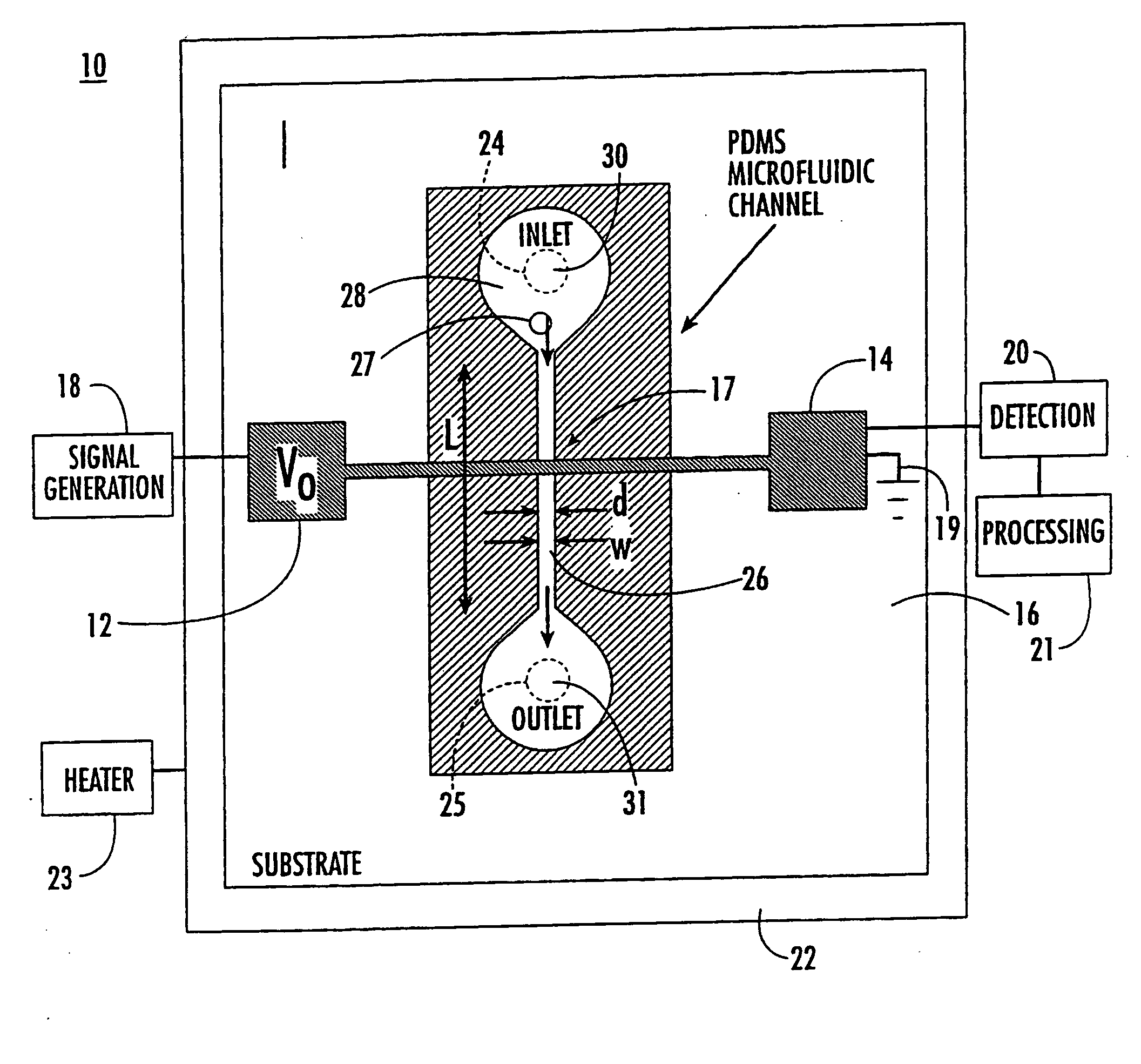
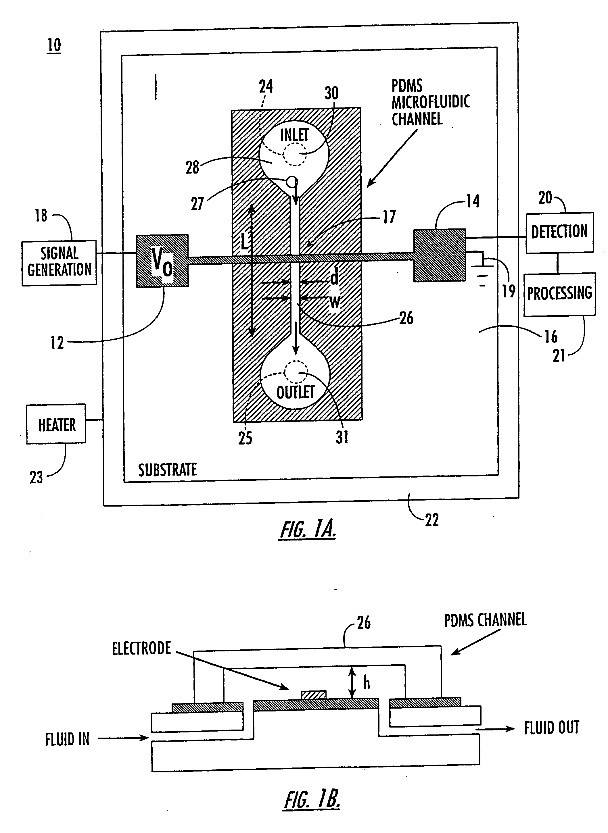
[0096] Microfluidic device 10 of the present invention is capable of detecting the capacitance of different fluids. The microfluidic device used for this experiment is shown in FIG. 1 having d 30 μm and h=30 μm.

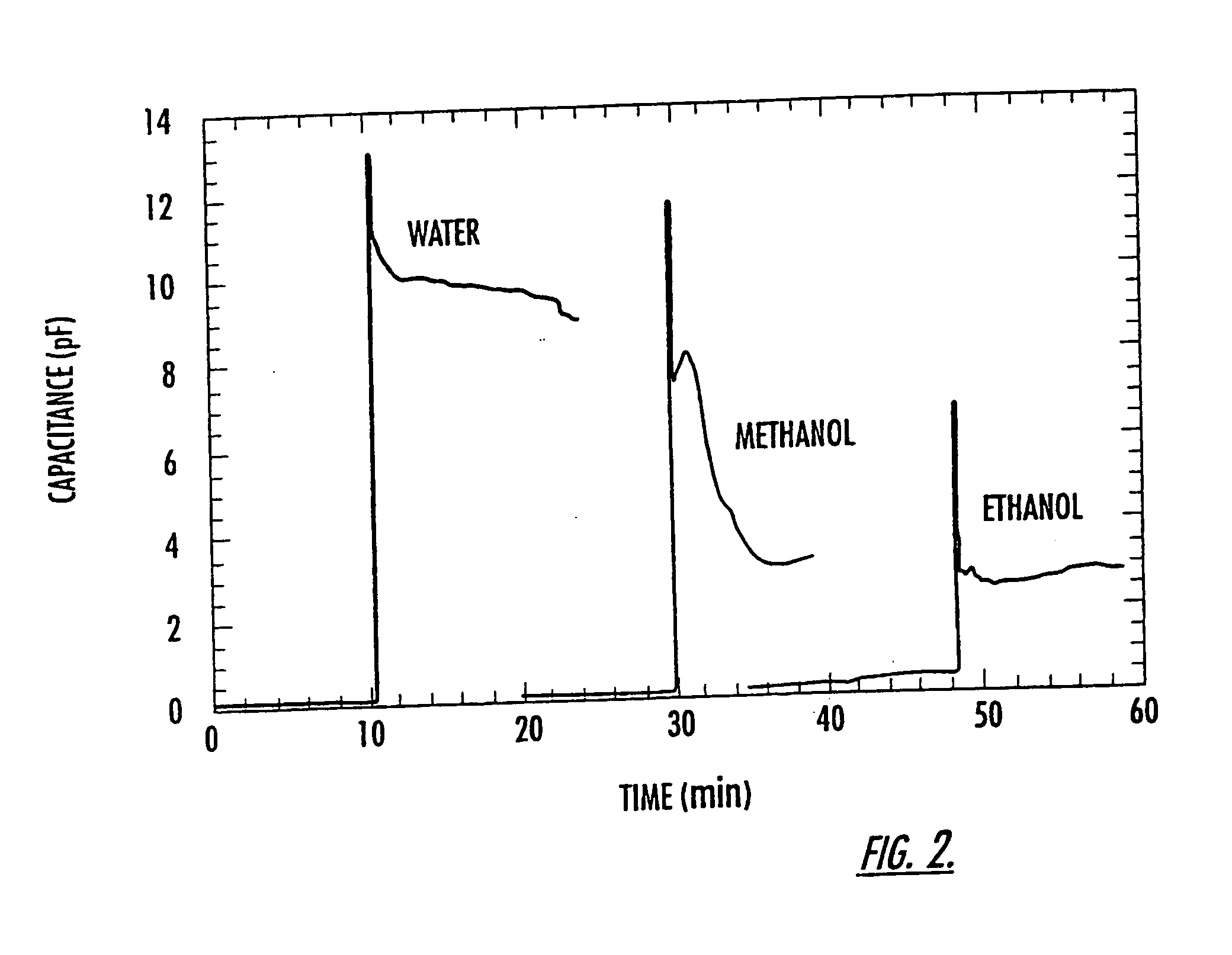
[0097] As shown in FIG. 2, there is a dramatic increase in both CT, and R once fluid flows past the electrodes (CTinitials measures 0.10 pF when the electrodes are dry). Although some settling time is needed for the device, the final values of CTinitials are 9, 3 and 2.5 pF for water, methanol, and ethanol, respectively. As expected, the change in capacitance ΔCT, scales with the dielectric constant of the fluid, i.e. (CT(final)−CT(initial)) / CT(initial)=for water is ˜90, that of methanol ˜30, and that of ethanol ˜25. Deviations from the actual dielectric constant of the three different solvents (water=80, methanol=33, and ethanol=24) are a result of stray capacitances, some of which are not affected by the fluid. These results demonstrate that...

example 2

Detecting Different Ionic Concentrations

[0098] Microfliudic device 10 of the present invention was used to detect differences in ionic strength of fluids. The microfluidic device used for this experiment is that shown in FIG. 1.

[0099]FIG. 3 shows the sensitivity of our device to different ionic concentrations. The buffer 2-(N morpholino) ethane-sulfonic acid (MES) was used at varying pH (pH −4.52, 5.07, and 6.18). As shown in the figure, the device is able to distinguish the different fluids and measure differences in ionic concentrations.

example 3

Detection of Single Mouse Myeloma Cells in a Fluid and Correlation Between Capacitance and Cellular DNA Content

[0100] The microfluidic device shown in FIG. 1 was used to detect individual, single cells and determine the content or amount of DNA in the individual cells. Also, the cell cycle stage for individual cells within a population of cells was determined and compared using flow cytometry and capacitance cytometry of the present invention. The cell cycle stage of the individual cells is determined by measuring the cellular DNA content.

[0101] Mouse myeloma cells (SP2 / 0), a malignant cell line, were grown in suspension to a density of approximately 105 cells / mL. The cells were then washed in phosphate-buffered saline (PBS) solution (pH 7.4), fixed in 75% ethanol at −20° C. for a minimum of 24 hours, washed again with PBS solution, treated with RNAase, and then washed and resuspended for storage in 75% ethanol. Standard analysis (FACScan flow cytometer, Becton Dickinson Immunocyt...


PUM

PropertyMeasurementUnit
distanceaaaaaaaaaa
widthaaaaaaaaaa
heightaaaaaaaaaa

Abstract

The present invention (also identified as “Capacitance cytometry”) relates to microfluidic and nanofluidic devices for detecting or measuring an electrical property of a fluid (liquid or aerosol), a single molecule, particle, or cell in fluid. In a particular embodiment, the devices detect or measure changes in capacitance of a fluid, molecule, particle or cell as it passes through the device. The invention relates to detection and measurement of single molecules, particularly biological molecules, and to methods of sequencing polynucleotide molecules (RNA or DNA) by detecting differentially labeled single nucleotides. Single molecule detection applications include DNA or RNA sequencing, detection of SNPs, protoemics, and particle sizing. The device can be used to determine cell DNA content, to analyze cell-cycle kinetics of cell populations, and to assay for abnormal changes in cell DNA content. Nano-microfluidic devices of this invention also have utility as detectors in molecular sorting systems and for detecting pathogens.

Description

RELATED APPLICATIONS [0001] This application claims priority to U.S. Provisional Application No. 60 / 150,899 filed Aug. 26, 1999, and U.S. Provisional Application No. 60 / 211063 entitled “Single Molecule Sequencing” filed Jun. 12, 2000, each of which are incorporated herein by reference in their entirety.GOVERNMENT SUPPORT [0002] This invention was made with U.S. governmental support under NSF Grant No. DMR 96-24536. The U.S. government has certain rights in the invention.FIELD OF THE INVENTION [0003] The present invention relates to microfluidic and nanofluidic electrical devices for detecting or measuring an electrical property of a fluid including a liquid or aerosol, a single molecule, or a single particle or cell in a fluid. In a particular embodiment, the devices detect or measure changes in capacitance of a fluid, gas, molecule, particle or cell as it passes through the device. The present invention also relates to the detection and measurement of single molecules, in particula...

Claims


Application Information

Patent Timeline
Patent Type & Authority Applications(United States)
IPC IPC(8): C12Q1/68C12M1/34G01N33/483B01L3/00C12Q1/00G01N15/10G01N27/02G01N27/22G01N27/447
CPCB01L3/502761G01N33/48721B01L2300/0645B01L2300/0896B01L2400/0415B01L2400/0487B82Y30/00C12Q1/68C12Q1/6825G01N15/1031G01N15/1056G01N2015/1006B01L2200/0647G01N33/48707C12Q2565/629C12Q2563/155C12Q2563/113
Inventor SOHN, LYDIA LEESALEH, OMAR A.KNIGHT, JAMES BRADFORDNOTTERMAN, DANIEL A.LANDWEBER, LAURA F.
Owner THE TRUSTEES FOR PRINCETON UNIV
Why Eureka
Try Eureka