Porous Coated Member and Manufacturing Method Thereof Using Cold Spray

a coating member and coating technology, applied in the field of coating members, can solve the problems of thermal impact on the mother material, process limits in application, stress may occur,

Inactive Publication Date: 2007-10-18
SKC SOLMICS
View PDF4 Cites 29 Cited by
  • Summary
  • Abstract
  • Description
  • Claims
  • Application Information

AI Technical Summary

Problems solved by technology

Furthermore, when mother material is joined with a different kind of material, stress may occur due to lattice misalignment at an interface.
However, these processes have limits in terms of application, or may cause thermal impact to the mother material or thermal deformation of the mother material.
Additionally, in practice, it is difficult to artificially control the porosity and pore distribution of the coating layer using the above processes.
As well, the thermal conductive metal coating layer which is applied to pipes of the conventional heat exchanger corrodes or is mossy on a surface thereof in a corrosive environment, such as waste water or sea water, thus it does not perform its function.
Accordingly, it is problematic in that durability is not assured.

Method used


Image

  • Porous Coated Member and Manufacturing Method Thereof Using Cold Spray
  • Porous Coated Member and Manufacturing Method Thereof Using Cold Spray
  • Porous Coated Member and Manufacturing Method Thereof Using Cold Spray

Examples


example 1

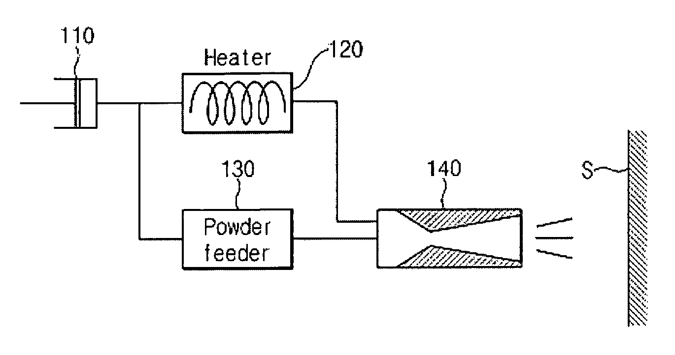
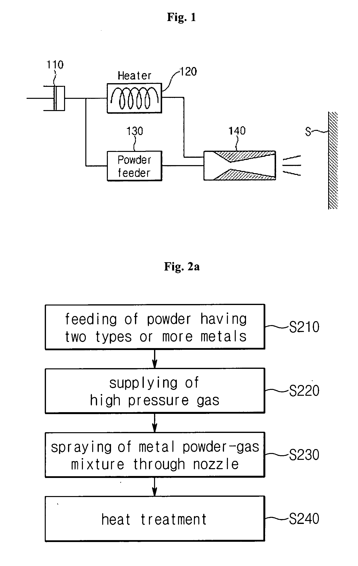
[0061] Mixture powder which includes Al powder and AlMg powder (eutectic temperature of about 400° C.) in a weight ratio of 50:50 (i.e. 0.5Al-0.5AlMg) and air at 7 atm were fed into a spraying nozzle to be applied on an aluminum substrate.

[0062] The resulting coating was heat treated at about 620° C. for 1 hour. The heat treated substrate was cut and polished, and cross section was observed using an optical microscope. FIG. 4 illustrates a picture of the cut surface of the resultant substrate.

[0063] From FIG. 4, it can be seen that the coating layer is nicely attached to the Al substrate. An interface between the Al substrate and the coating layer is apparent due to pores (black portions) trapped in the coating layer. The pores were not observed during the coating, but were generated after the heat treatment.

example 2

[0064] A coating layer was produced under the same conditions as example 1 except that the weight of AlMg increased in the mixture powder so that the metal powder had a composition of 0.3Al-0.7AlMg. The coating layer was heat treated, a section was observed using an optical microscope, and the results are shown in FIG. 5.

[0065] In comparison with FIG. 4, from FIG. 5, it can be seen that the size of the pore is increased, and an increase in porosity can be confirmed even with the naked eye.

example 3

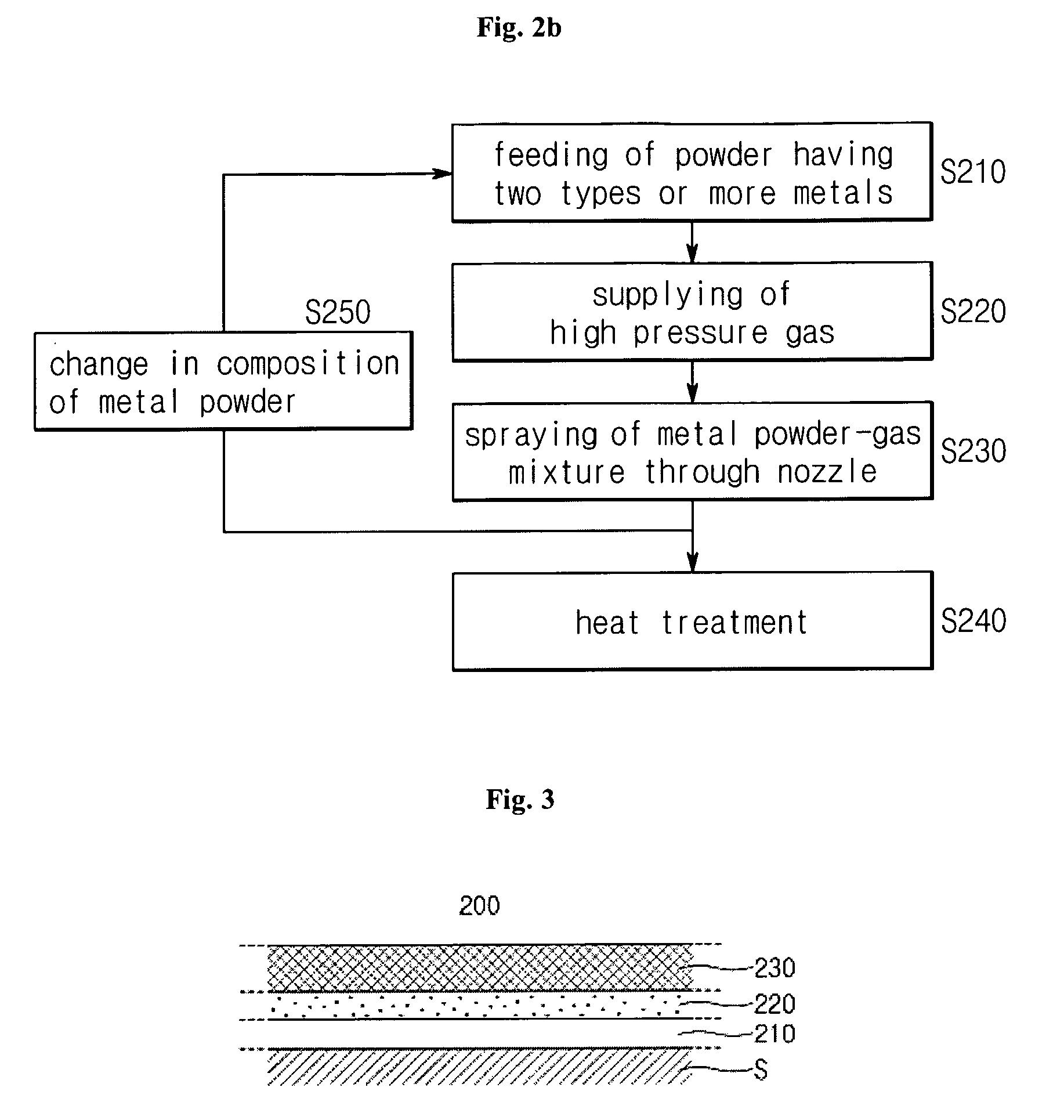
[0066] A coating layer was formed in such a way that Al powder / AlMg powder / Al powder / AlMg powder / Al powder were sequentially layered. The remaining coating conditions were the same as example 1. Subsequently, the resulting coating layer was heat treated at 620° C. for 1 hour.

[0067]FIG. 6 is an optical microscope picture showing a section of a heat treated substrate. As shown in the drawing, pores were scarcely observed in the Al layer, but frequently observed in the AlMg layer.


PUM

PropertyMeasurementUnit
melting pointaaaaaaaaaa
pressureaaaaaaaaaa
particle sizeaaaaaaaaaa

Abstract

Disclosed is a coated member on which a porous metal coating layer is formed and a method of producing the same. The method comprises providing the mother material, feeding powder having a metal composition, which includes at least two different metals selected from the group consisting of Al, Mg, Zn, and Sn and which is expressed by xA-(1−x)B (0<x<1, where x is a weight ratio of A and B), onto the mother material, supplying high pressure gas to the powder, applying the metal powder using on the mother material by spraying the metal powder using the high pressure gas through an supersonic nozzle, and heat-treating the coated mother material to form the porous coating layer. In the method, it is possible to freely control the pore size and porosity of the coated member. Accordingly, it is available to various members for thermal and mechanical applications.

Description

TECHNICAL FIELD [0001] The present invention relates, in general, to a coated member on which a porous coating layer is formed and a method of producing the same and, more particularly, to a method of forming a porous coating layer on a surface of mother material using a low temperature spraying process and a coated member in which a pore distribution and a size of the coating layer are controlled. BACKGROUND ART [0002] Formed on a surface of a member, a porous coating layer improves thermal and mechanical properties of the member. [0003] For example, if a porous coating layer which includes open pores communicating with each other is formed on the surface of a heat exchanger, the heat exchanger has an increased area of contact with surrounding air, thereby assuring efficient heat exchanging performance. Meanwhile, sometimes, it is expected for a friction member to have low strength and hardness depending on its relationship with surrounding components. The porous coating layer can ...

Claims


Application Information

Patent Timeline
Patent Type & Authority Applications(United States)
IPC IPC(8): C23C24/04C23C26/00C23C4/00C23C28/02
CPCC23C4/12C23C4/18C23C28/021C23C28/023C23C28/028C23C24/04A62B7/02A62B7/10F21V33/0068
Inventor KO, KYUNG-HYUNLEE, HA-YONG
Owner SKC SOLMICS
Why Eureka
Try Eureka