Control system for multiphase rotary electric machines

a control system and multi-phase technology, applied in the direction of electronic commutators, motor/generator/converter stoppers, dynamo-electric converter control, etc., can solve the problems of increasing the number of switchings of each switching element, increasing the torque deviation, and difficult for the three-phase rotary electric machine to generate the request torqu

Inactive Publication Date: 2007-10-18
DENSO CORP
View PDF13 Cites 22 Cited by
  • Summary
  • Abstract
  • Description
  • Claims
  • Application Information

AI Technical Summary

Benefits of technology

[0019]According to one aspect of the present invention, there is provided a control system. The control system is designed to control, based on a comparison between a waved real current to be supplied to a multiphase rotary electric machine and a hysteresis region established by a waved command signal, a switching timing of a switching element of an inverter to which a direct current voltage is applied to thereby match the waved real current with a waved request current. The waved real current allows a portion of the multiphase rotary electric machine to rotate. The waved command signal is set to the waved request current. The waved request current is required for the multiphase

Problems solved by technology

This may make it difficult for the three-phase rotary electric machine to generate the request torque.
In the former method, however, the reduction in the hysteresis width of the command current wave may cause an increase in the number of switchings of each switching element.
The reduction in the voltage utilization factor may cause

Method used


Image

  • Control system for multiphase rotary electric machines
  • Control system for multiphase rotary electric machines
  • Control system for multiphase rotary electric machines

Examples


first embodiment

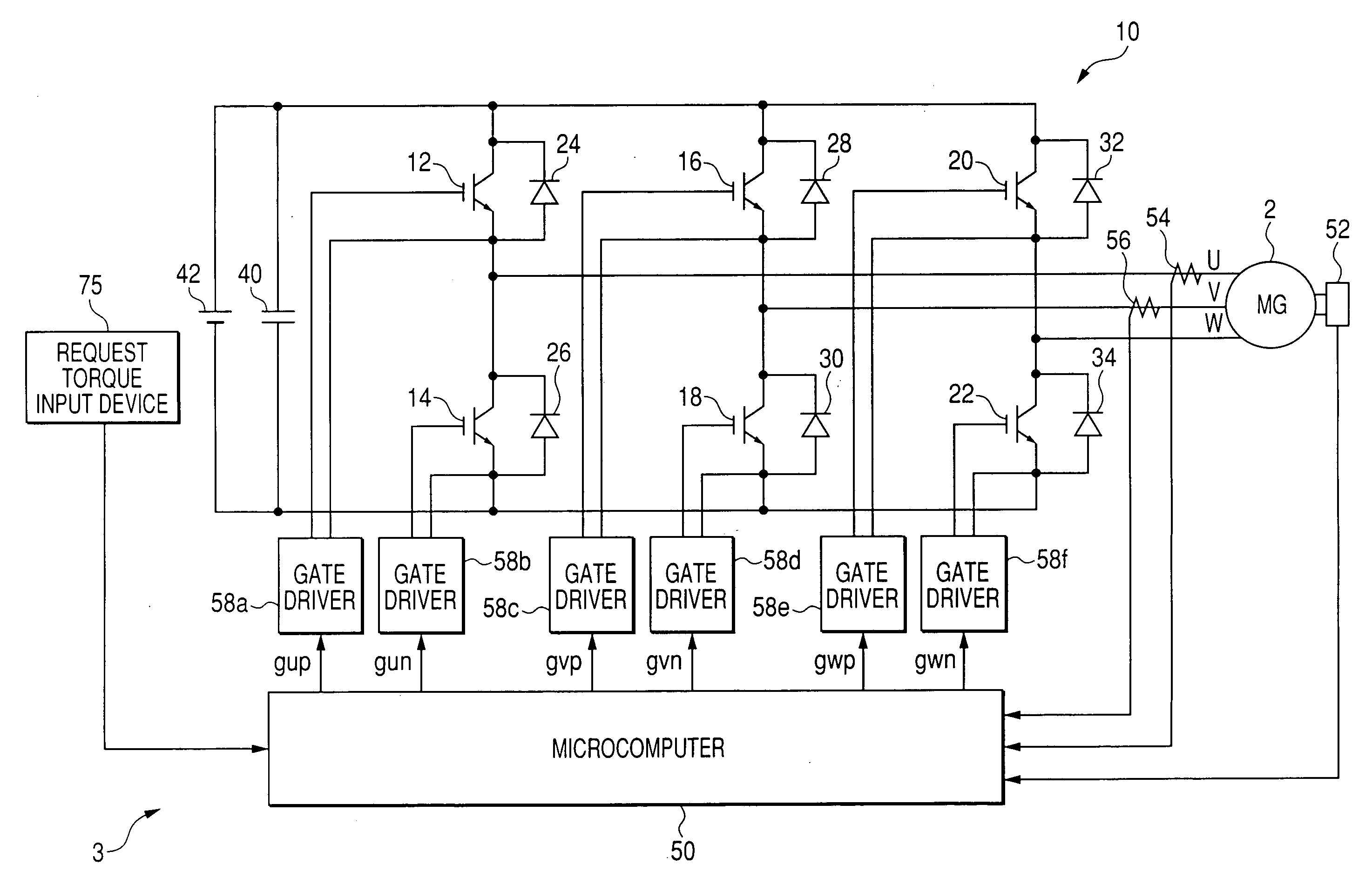
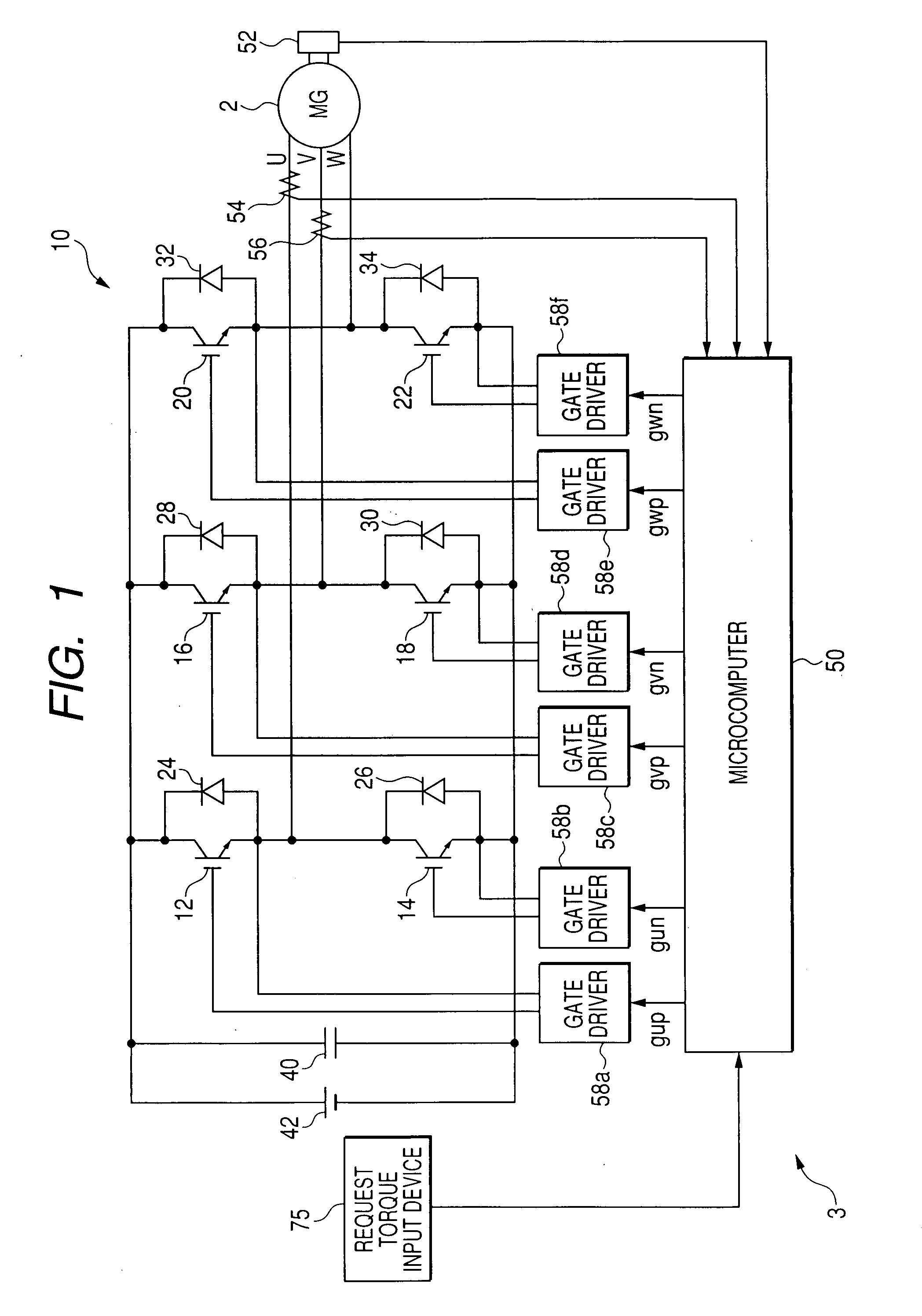
[0053]Referring to the drawings, in which like reference characters refer to like parts in several figures, particularly to FIG. 1, there is illustrated a three-phase DC (Direct Current) brushless motor, referred to simply as “motor”2 and a control system 3 for controlling the motor 2.

[0054]For example, the motor 2 is provided with an annular rotor whose rotor core is fixedly fitted around the outer periphery of a crankshaft of an engine installed in the hybrid vehicle.

[0055]The rotor core of the rotor is provided at its circumferential portion with a number of N and S pole pairs arranged at given intervals. The rotor has a direct axis (d-axis) in line with a rotor N pole center line, and has a quadrature axis (q-axis) whose phase is π / 2 radian electric angle leading with respect to a corresponding d-axis during rotation of the rotor.

[0056]The stator includes a stator core with, for example, an annular shape in its lateral cross section. The stator core is disposed around the outer ...

second embodiment

[0146]A control system for a motor according to a second embodiment of the present invention will be described hereinafter. The structure of the control system is substantially identical to that of the control system 3 according to the first embodiment.

[0147]Thus, like reference characters are assigned to like parts in the control systems according to the first and second embodiments, and therefore, descriptions of the structure of control system according to the second embodiment are omitted.

[0148]FIG. 9 schematically illustrates functional modules of a microcomputer 50A equivalent to tasks to be executed thereby according to the second embodiment.

[0149]The microcomputer 50A includes a command current calculator 80 in place of the first d-q axis command current calculator 62, the second d-q axis command current calculator 64, and the current value selector 66.

[0150]The command current calculator 80 works to calculate the first command values idc1 and iqc1 and the second command val...

third embodiment

[0174]A control system for a motor according to a third embodiment of the present invention will be described hereinafter. The structure of the control system is substantially identical to that of the control system 3 according to the first embodiment.

[0175]Thus, like reference characters are assigned to like parts in the control systems according to the first and third embodiments, and therefore, descriptions of the structure of control system according to the third embodiment are omitted.

[0176]FIG. 13 schematically illustrates functional modules of a microcomputer 50B equivalent to tasks to be executed thereby according to the third embodiment.

[0177]The microcomputer 50B includes an amplitude correction-coefficient calculator (COEFFICIENT CALCULATOR) 82, a multiplier 84, a multiplier 86, a phase correction-value calculator 88, and an adder 90 in place of the second d-q axis command current calculator 64.

[0178]A first d-q axis command current calculator 62A has first command value ...


PUM


Abstract

A control system controls, based on a comparison between a waved real current to be supplied to a multiphase rotary electric machine and a hysteresis region established by a waved command signal, a switching timing of a switching element of an inverter to which a direct current voltage is applied to thereby match the waved real current with a waved request current. A determining unit determines whether a workload associated with rotation of the portion of the multiphase rotary electric machine is equal to or greater than a corresponding predetermined value. When it is determined that the workload is equal to or greater than the predetermined value, a changing unit changes the waved command signal from being set to the waved request current so as to determine the switching timing of the switching element based on a positional relation between the waved request current and the changed waved command signal.

Description

CROSS REFERENCE TO RELATED APPLICATIONS[0001]This application is based on Japanese Patent Application 2006-112128 filed on Apr. 14, 2006. This application claims the benefit of priority from the Japanese Patent Application, so that the descriptions of which are all incorporated herein by reference.FIELD OF THE INVENTION[0002]The present invention relates to control systems for multiphase rotary electric machines, which are designed to carry out instantaneous current control of switching elements of an inverter.BACKGROUND OF THE INVENTION[0003]US Patent Publication No. 5,942,876 corresponding to Japanese Unexamined Patent Publication No. H10-174453 discloses control systems for a three-phase rotary electric machine. A typical example of the control systems is designed to carry out a feedback control for a current to be supplied to each phase of the three-phase rotary electric machine.[0004]In the feedback control, during normal operation of the three-phase rotary electric machine, th...

Claims


Application Information

Patent Timeline
IPC IPC(8): H02P7/06H02P6/08H02P6/06H02P6/17H02P6/28
CPCH02P23/0036H02P21/0003H02P23/0004
Inventor YAMADA, TAKAHIROTSUJI, HIROYA
Owner DENSO CORP
Why Eureka
Try Eureka