Polarization controlling apparatus and polarization operation apparatus

a technology of polarization control and operation apparatus, which is applied in the direction of instruments, non-linear optics, optics, etc., can solve the problems of high-speed operation, increase of apparatus scale, and inability to avoid increase of power dissipation, so as to achieve the effect of increasing the degree of freedom in apparatus design, increasing the power dissipation, and increasing the apparatus scal

Inactive Publication Date: 2007-10-18
FUJITSU LTD
View PDF4 Cites 0 Cited by
  • Summary
  • Abstract
  • Description
  • Claims
  • Application Information

AI Technical Summary

Benefits of technology

[0017]It is an object of the present invention to provide a polarization controlling apparatus wherein the degree of freedom in apparatus design can be enhanced while increase of the power dissipation and increase of the apparatus scale are suppressed and a high-speed operation can be achieved.

Problems solved by technology

However, if the number of turns of the winding is increased, then the inductance of the coil increases, which makes a high-speed operation difficult, and besides, increase of the apparatus scale cannot be avoided.
However, increase of the power dissipation cannot be avoided.
Accordingly, both of increase of the number of turns of the winding and increase of the current to be supplied to the winding have a factor of making an obstacle to the apparatus design.
Further, such a polarization scrambler of a configuration wherein one wave plate is interposed between two or four Faraday rotators as disclosed in Patent Document 3 or 4 fails to sufficiently implement various polarization states.

Method used


Image

  • Polarization controlling apparatus and polarization operation apparatus
  • Polarization controlling apparatus and polarization operation apparatus
  • Polarization controlling apparatus and polarization operation apparatus

Examples


first embodiment

A1. First Embodiment

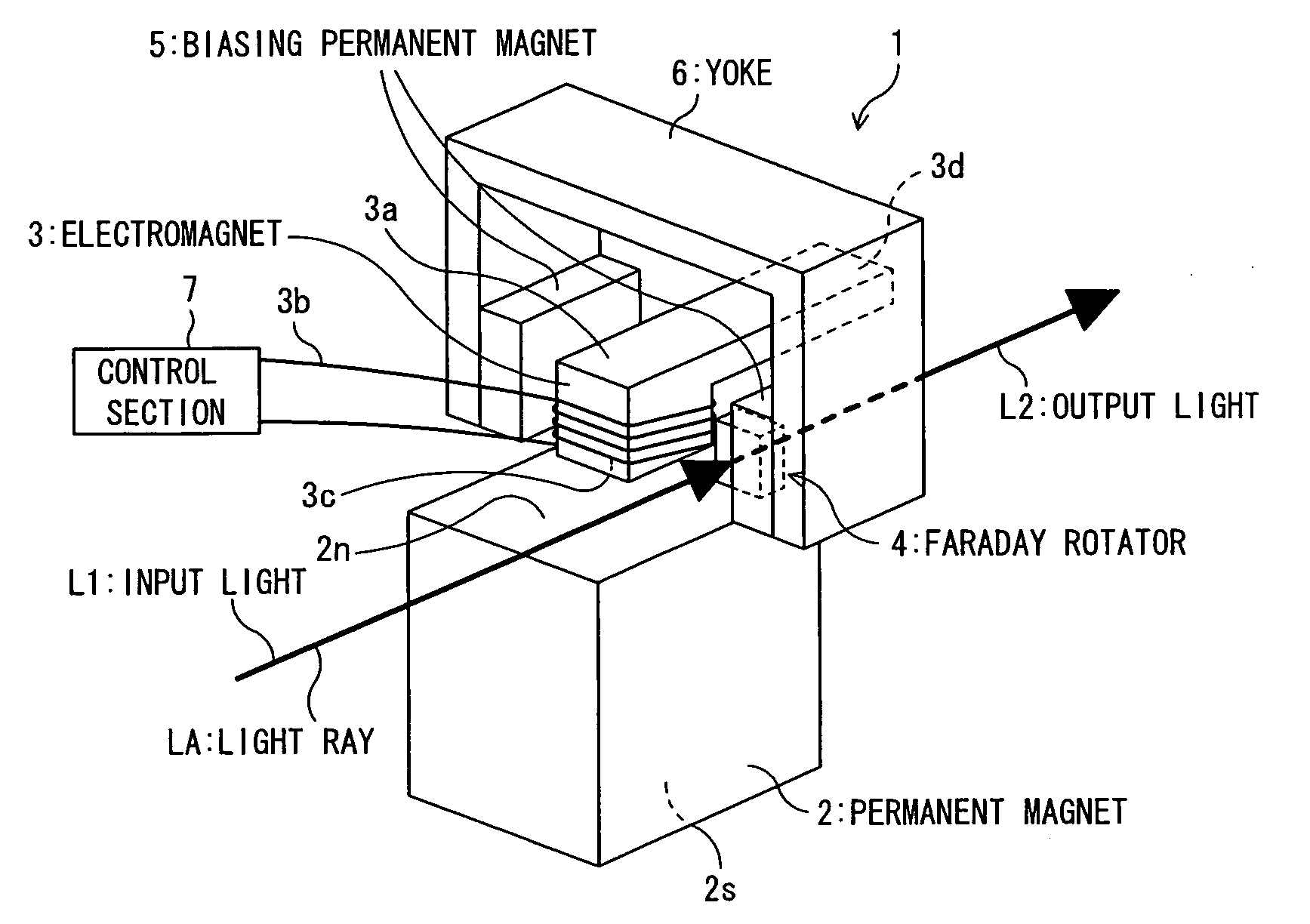
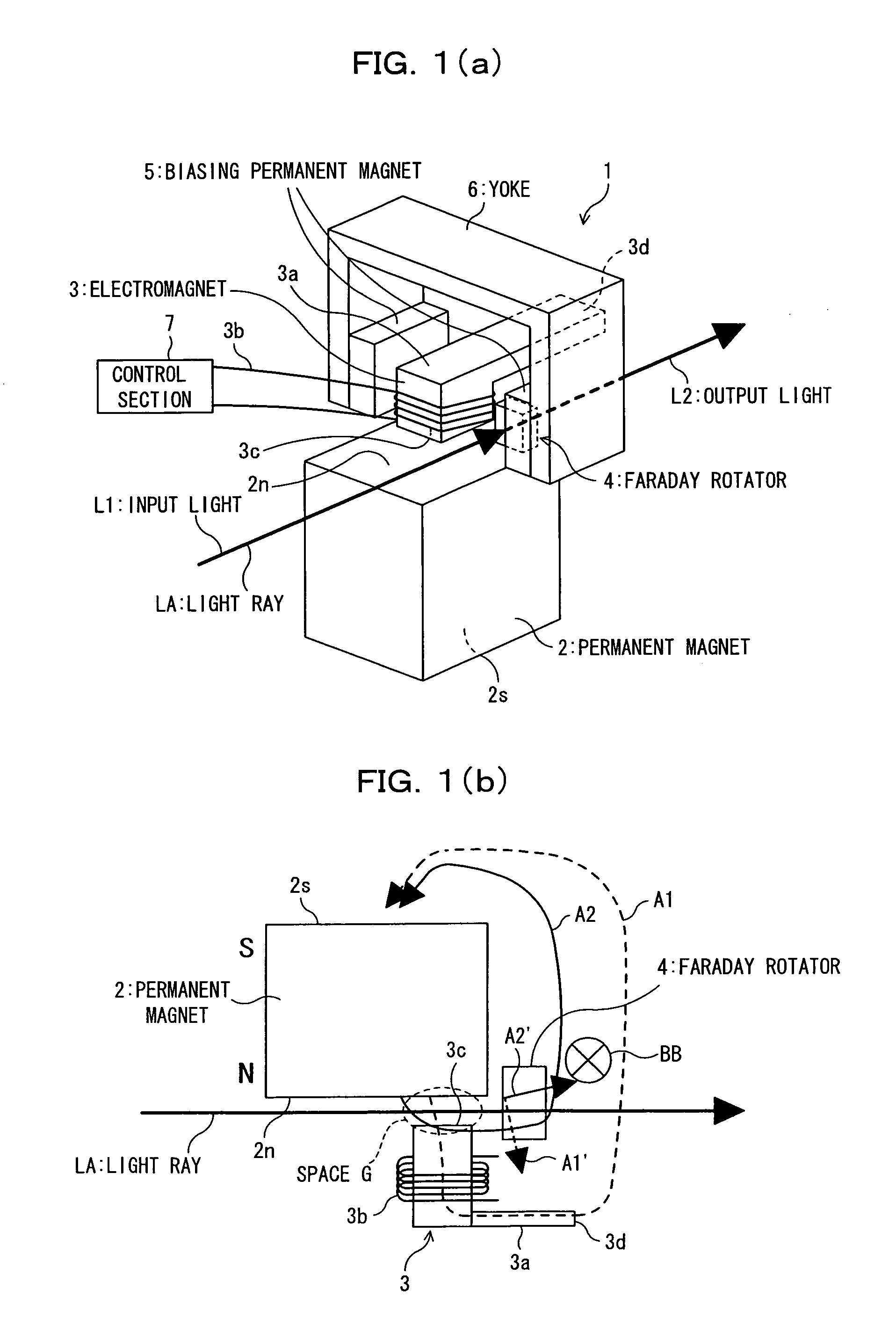
[0052]FIG. 1(a) is a schematic perspective view showing an example of a configuration of a polarization controlling apparatus according to a first embodiment of the present invention. Referring to FIG. 1(a), the polarization controlling apparatus 1 shown includes a permanent magnet 2, an L-shaped electromagnet 3 and a Faraday rotator 4, and further includes a pair of permanent magnets 5 for biasing and a yoke 6. The permanent magnet 2 may be a rare earth magnet such as, for example, a Nd magnet or a Sm—Co magnet, a ferrite magnet, an alnico magnet or a bond type magnet whose parent body is made of a high molecular material which contains permanent magnet powder made of any of the materials mentioned.

[0053]The electromagnet 3 includes an L-shaped core member 3a formed from, for example, a ferrite member, and a winding (coil) 3b formed from a conductor wound on one side of the L shape of the core member 3a. The magnitude of a magnetic field to be generated in an op...

second embodiment

B1. Second Embodiment

[0085]FIG. 9 is a schematic perspective view showing an example of a configuration of a polarization control apparatus 10 according to a second embodiment of the present invention, and FIG. 10 is a schematic view illustrating a variation of a magnetic field in response to a variation of current to flow through a winding 13b of an electromagnet 13 in the polarization control apparatus 10 according to the second embodiment and is a view showing the polarization control apparatus 10 as viewed in a direction from above in FIG. 9.

[0086]Referring first to FIG. 9, the polarization control apparatus 10 shown includes a permanent magnet 12, an L-shaped electromagnet 13 and a control section 17 disposed in different arrangement from that of the first embodiment described hereinabove. The polarization control apparatus 10 further includes a Faraday rotator 4 having a reflecting member 8 formed on a face 4b thereof, a pair of biasing permanent magnets 5 and a yoke 6. The pe...

third embodiment

C1. Third Embodiment

[0129]FIG. 22 shows a polarization control apparatus 20 according to a third embodiment of the present invention. Referring to FIG. 22, the polarization control apparatus 20 shown is different from the polarization control apparatus 10 (refer to FIG. 9) according to the second embodiment described hereinabove in that it does not include the L-shaped electromagnet 13 which contacts with the N pole of the permanent magnet 12 but includes an electromagnet 23 which uses a magnetic field by the permanent magnet 12 so as to lead a magnetic field for exerting a Faraday rotation effect of light to the Faraday rotator 4.

[0130]The polarization control apparatus 20 according to the third embodiment includes, in addition to the electromagnet 23 described above and a control section 27 for driving the electromagnet 23, a permanent magnet 12, a Faraday rotator 4 and a reflecting member 8 as well as biasing permanent magnets 5 and a yoke 6 not shown which are similar to those d...


PUM

PropertyMeasurementUnit
magnetic fieldaaaaaaaaaa
rotation effectaaaaaaaaaa
magneticaaaaaaaaaa

Abstract

A polarization controlling apparatus is disclosed, which enhances the degree of freedom in apparatus design.
The polarization controlling apparatus includes a permanent magnet itself or a permanent magnet to which a part capable of being magnetized is applied, an electromagnet capable of changing the magnitude of a magnetic field to be generated thereby, and a Faraday rotation effect element, disposed at a position at which an interaction magnetic field produced by an interaction between a magnetic field generated by the permanent magnet and a magnetic field generated by the electromagnet acts, for producing a Faraday rotation effect on inputted light by means of the interaction magnetic field. The magnitude of the interaction magnetic field in the Faraday rotation effect element is varied by a magnetic field component generated by the electromagnet to vary the amount of the Faraday rotation effect to be had on the inputted light.

Description

BACKGROUND OF THE INVENTION[0001]1) Field of the Invention[0002]This invention relates to a polarization controlling apparatus and a polarization operation apparatus suitable for use in the fields of optical communication, optical signal processing, optical measurement and so forth, and more particularly to a polarization controlling apparatus and a polarization operation apparatus suitable for use as a component of a high-speed polarization scrambler in optical communication.[0003]2) Description of the Related Art[0004]A Faraday rotator is an optical device which rotates the polarization state of input light using a Faraday effect of rotating the polarization state of light using a magnetic field applied in the direction of an optical axis of the light. And the Faraday rotator is applied not only to optical isolators and circulators but also to polarization scramblers and like devices. Polarization scrambler to which the Faraday rotator is applied is demanded a performance of being...

Claims


Application Information

Patent Timeline
Patent Type & Authority Applications(United States)
IPC IPC(8): G02F1/09
CPCG02F1/0136G02F2201/17G02F2001/0139G02F1/09G02F1/0139
Inventor HIRONISHI, KAZUOFUKUSHIMA, NOBUHIRORASMUSSEN, JENS
Owner FUJITSU LTD
Why Eureka
Try Eureka