Tunable negative refractive index composite

Inactive Publication Date: 2007-10-18
UNITED STATES OF AMERICA
View PDF4 Cites 24 Cited by
  • Summary
  • Abstract
  • Description
  • Claims
  • Application Information

AI Technical Summary

Benefits of technology

[0003] The invention comprises a composite comprising a stack of a repeating pattern of layers of: a layer of a nonconductive magnetic material, a first layer of a dielectric material; a layer of a semiconducting material

Problems solved by technology

These structures are generally fragile, have a narrow band pass and cannot be dynamically tuned in frequency of operation.
Similarly, the negative refractive pass bands of photonic crystal materials are not dynamically tunable.
In ad

Method used


Image

  • Tunable negative refractive index composite
  • Tunable negative refractive index composite
  • Tunable negative refractive index composite

Examples


Embodiment Construction

[0011] In the following description, for purposes of explanation and not limitation, specific details are set forth in order to provide a thorough understanding of the present invention. However, it will be apparent to one skilled in the art that the present invention may be practiced in other embodiments that depart from these specific details. In other instances, detailed descriptions of well-known methods and devices are omitted so as to not obscure the description of the present invention with unnecessary detail.

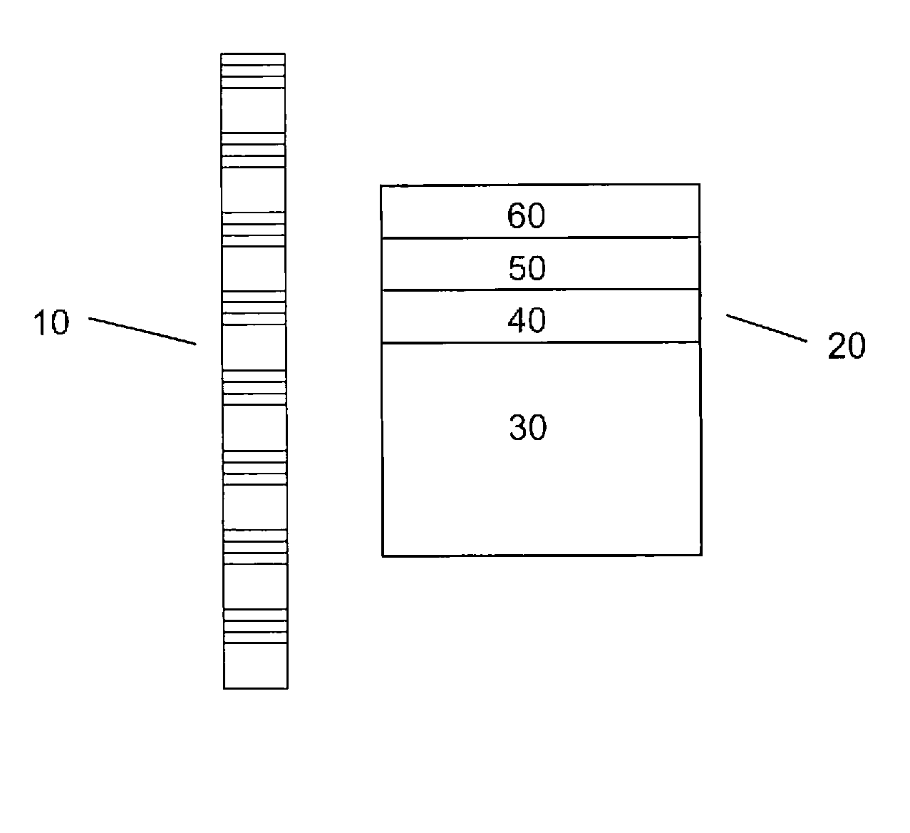
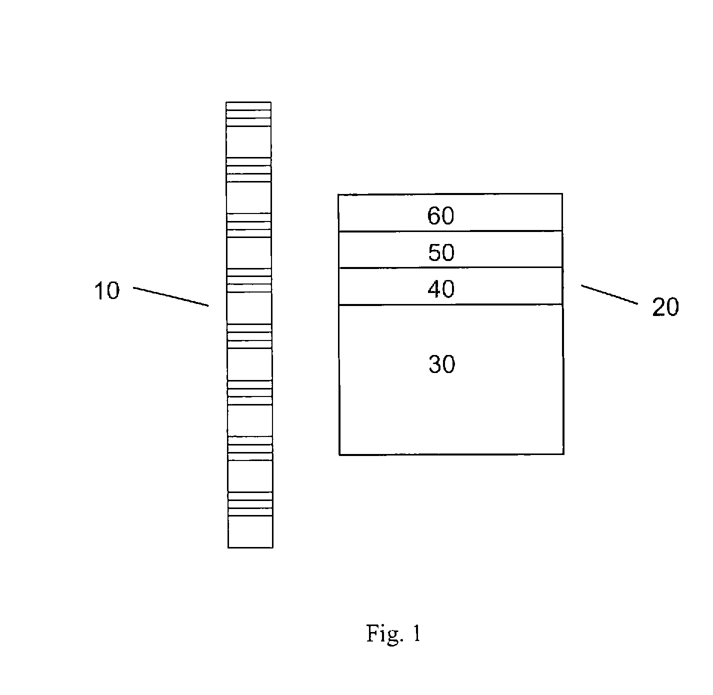
[0012] The invention may provide a durable and tunable composite structure for the production of negative index of refraction or small positive index components for microwave / millimeter wave optics applications and for phase compensation in optic or guided wave structures. The desired frequency band of negative index of refraction and / or small positive index of refraction is referred to herein as the “region of operation.”

[0013] The composite comprises multiple layers o...


PUM

PropertyMeasurementUnit
Fractionaaaaaaaaaa
Thicknessaaaaaaaaaa
Dielectric polarization enthalpyaaaaaaaaaa

Abstract

A composite having a stack of a repeating pattern of layers of: a layer of a nonconductive magnetic material, a first layer of a dielectric material; a layer of a semiconducting material; and a second layer of the dielectric material. The composite has a magnetic resonance frequency and a magnetic anti-resonance frequency and a plasma frequency at higher frequencies than the magnetic resonance frequency.

Description

FIELD OF THE INVENTION [0001] The invention generally relates to negative index of refraction composites. DESCRIPTION OF RELATED ART [0002] Negative index of refraction has been demonstrated in conductive element composite structures and negative refraction (an effective negative refractive index) has been observed in photonic crystal media. The first such conductive element composite consisted of split ring resonators and wire arrays printed on standard circuit board. These structures are generally fragile, have a narrow band pass and cannot be dynamically tuned in frequency of operation. Similarly, the negative refractive pass bands of photonic crystal materials are not dynamically tunable. In both cases tuning the pass band requires a re-fabrication of the composite. In addition unit cells of photonic crystal negative index structures are of the order of half wavelength of the electromagnetic wave, causing large spurious diffractive effects and other difficulties in the fabricati...

Claims


Application Information

Patent Timeline
IPC IPC(8): G01R33/02G02B1/10
CPCG02B1/02Y10T428/325G02B6/10G02B1/007
Inventor RACHFORD, FREDERIC J.
Owner UNITED STATES OF AMERICA
Why Eureka
Try Eureka