Downhole Pressure Pulse Activated by Jack Element

a technology of jack element and downhole pressure pulse, which is applied in the direction of borehole/well accessories, survey, instruments, etc., can solve the problems of reducing the efficiency of indentation and shear cutting, slowed conventional drilling, and strength and plasticity of rock

Inactive Publication Date: 2007-10-18
SCHLUMBERGER TECH CORP
View PDF4 Cites 55 Cited by
  • Summary
  • Abstract
  • Description
  • Claims
  • Application Information

AI Technical Summary

Benefits of technology

[0006] In one aspect of the present invention, a method has steps for forming a wellbore with a tool string bit having a body intermediate a shank and a working face. The bit body has a fluid passageway and at least a portion of a jack element is disposed within the body. The jack element also has an end forming at least a portion of a relief mechanism in the fluid passageway and a distal end substantially protruding from the working face. The bit connected to a tool string is deployed into a wellbore. Fluid is passed through the fluid passageway. A bottom of the wellbore is destructed by pulsing the fluid traveling through the passageway by opening and closing the relief mechanism. The pulsing fluid generates a suction pressure pulse in the wellbore. It is believed that a suction pressure pulse may be an efficient way of breaking up a downhole formation.
[0009] When closed, the relief mechanism may restrict all flow within the fluid passageway or may restrict only a portion of the flow within the fluid passageway. The tool string may also have a sensor adapted to receive acoustic reflections produced by either the pulse that propagates into the formation or the vibrations of the jack element. The sensor may be beneficial in determining formation characteristics.

Problems solved by technology

However, this conventional drilling is slowed by the confining pressure exerted by a column of mud in the wellbore.
The confining pressure of the mud increases the strength and plasticity of rock, reducing the efficiency of indentation and shear cutting.
However, UBD may reduce the stability of the wellbore, thereby increasing the risk of the wellbore collapsing in on itself because of the low pressure over the entire open section of the hole.

Method used


Image

  • Downhole Pressure Pulse Activated by Jack Element
  • Downhole Pressure Pulse Activated by Jack Element
  • Downhole Pressure Pulse Activated by Jack Element

Examples


Embodiment Construction

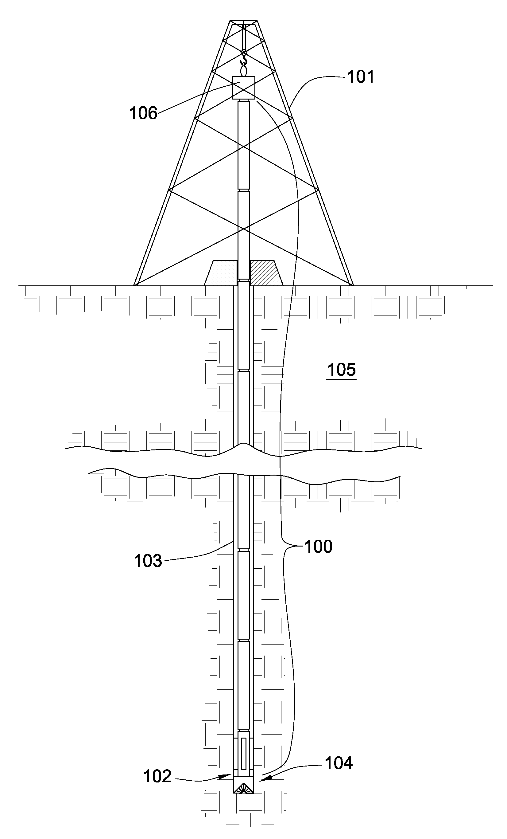
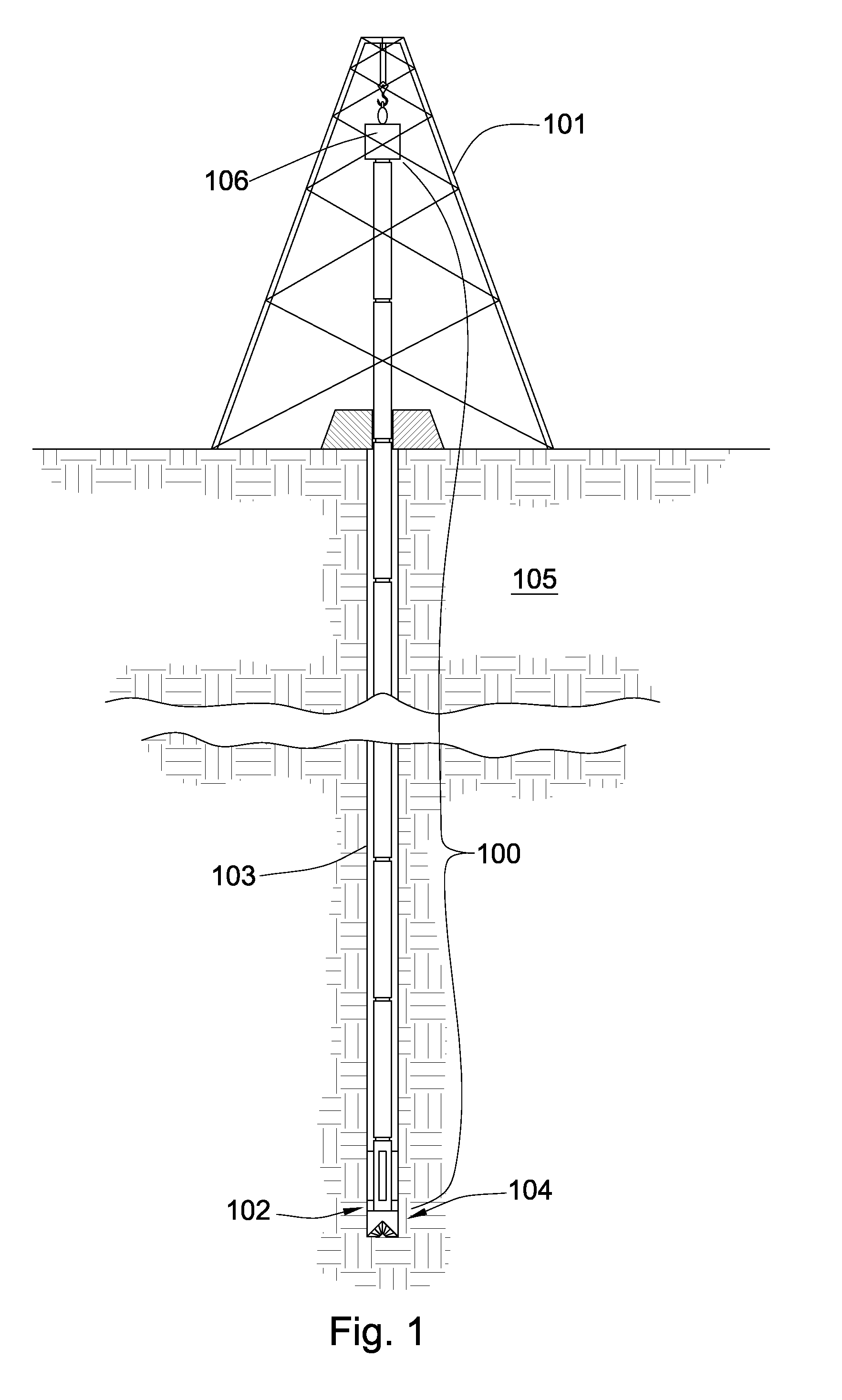
[0022]FIG. 1 shows a cross-sectional diagram of an embodiment of a tool string 100 suspended by a derrick 101. A bottom hole assembly 102 is located at the bottom of a wellbore 103 and comprises a tool string bit 104. As the tool string bit 104 rotates downhole the tool string 100 advances farther into the earth. The tool string 100 may penetrate soft or hard subterranean formations 105. The bottom-hole assembly 102 and / or downhole components may comprise data acquisition devices which may gather data. The data may be sent to the surface via a transmission system to a data swivel 106. The data swivel 106 may send the data to the surface equipment. Further, the surface equipment may send data and / or power to downhole tools and / or the bottom-hole assembly 102. U.S. Pat. No. 6,670,880 which is herein incorporated by reference for all that it contains, discloses a telemetry system that may be compatible with the present invention; however, other forms of telemetry may also be compatible...


PUM


Abstract

In one aspect of the present invention, a method has steps for forming a wellbore with a tool string bit having a body intermediate a shank and a working face. The bit body has a fluid passageway and at least a portion of a jack element is disposed within the body. The jack element also has an end forming at least a portion of a relief mechanism in the fluid passageway and a distal end substantially protruding from the working face. The bit connected to a tool string is deployed into a wellbore. Fluid is passed through the fluid passageway. A bottom of the wellbore is destructed by pulsing the fluid traveling through the passageway by opening and closing the relief mechanism.

Description

CROSS REFERENCE TO RELATED APPLICATIONS [0001] This Patent Application is a continuation-in-part of U.S. patent application Ser. No. 11 / 761,095 filed on Jun. 11, 2007 and entitled Drill Bit Transducer Device. U.S. patent application Ser. No. 11 / 761,095 is a continuation-in-part of U.S. patent application Ser. No. 11 / 750,700 filed on May 18, 2007 and entitled Jack Element with a Stop-off. U.S. patent application Ser. No. 11 / 750,700 a continuation-in-part of U.S. patent application Ser. No. 11 / 737,034 filed on Apr. 18, 2007 and entitled Rotary Valve for Steering a Drill Bit. U.S. patent application Ser. No. 11 / 737,034 is a continuation in-part of U.S. patent application Ser. No. 11 / 686,638 filed on Mar. 15, 2007 and entitled Rotary Valve for a Jack Hammer. U.S. patent application Ser. No. 11 / 686,638 is a continuation in-part of U.S. patent application Ser. No. 11 / 680,997 filed on Mar. 1, 2007 and entitled Bi-center Drill Bit. U.S. patent application Ser. No. 11 / 680,997 is a continuati...

Claims


Application Information

Patent Timeline
Patent Type & Authority Applications(United States)
IPC IPC(8): E21B7/00E21B21/08G01S15/00
CPCE21B7/24G01S15/88E21B10/602E21B10/54
Inventor HALL, DAVID R.HENDENGREN, CARLA
Owner SCHLUMBERGER TECH CORP
Why Eureka
Try Eureka