Direct-conversion receiver and sub-harmonic frequency mixer thereof

a direct-conversion receiver and sub-harmonic frequency technology, applied in the field of wireless reception units and sub-harmonic frequency mixers of direct-conversion receivers, can solve the problems of large power loss in lo signals, high power consumption, complicated whole receiver structure, etc., and achieve low supply voltage and sufficient output voltage swing

Inactive Publication Date: 2007-10-18
INFORMATION & COMMUNICATIIONS UNVERSITY EDUCATIONS UNIV EDUCATIONAL FOUNDATIION
View PDF24 Cites 23 Cited by
  • Summary
  • Abstract
  • Description
  • Claims
  • Application Information

AI Technical Summary

Benefits of technology

[0009] Therefore, an object of the present invention is to provide a direct-conversion receiver capable of ensuring a sufficient output voltage swing and of driving at a low supply voltage.

Problems solved by technology

The poly-phase filter 130 is composed of a multi-stage resistor-capacitor circuit that causes large loss, which results in a large power loss in the LO signals.
Such an additional LO amplifier 140, 171, 172, 174 and 177 makes not only the whole receiver structure complicated but also the power consumption high.
However, such a multi-stage fashion can not guarantee a sufficient voltage swing at its output end under a limited supply voltage and thus makes the inevitable use of high supply voltage.

Method used


Image

  • Direct-conversion receiver and sub-harmonic frequency mixer thereof
  • Direct-conversion receiver and sub-harmonic frequency mixer thereof
  • Direct-conversion receiver and sub-harmonic frequency mixer thereof

Examples


Embodiment Construction

[0020] Hereinafter, preferred embodiments of the present invention will be described in detail with reference to the accompanying drawings.

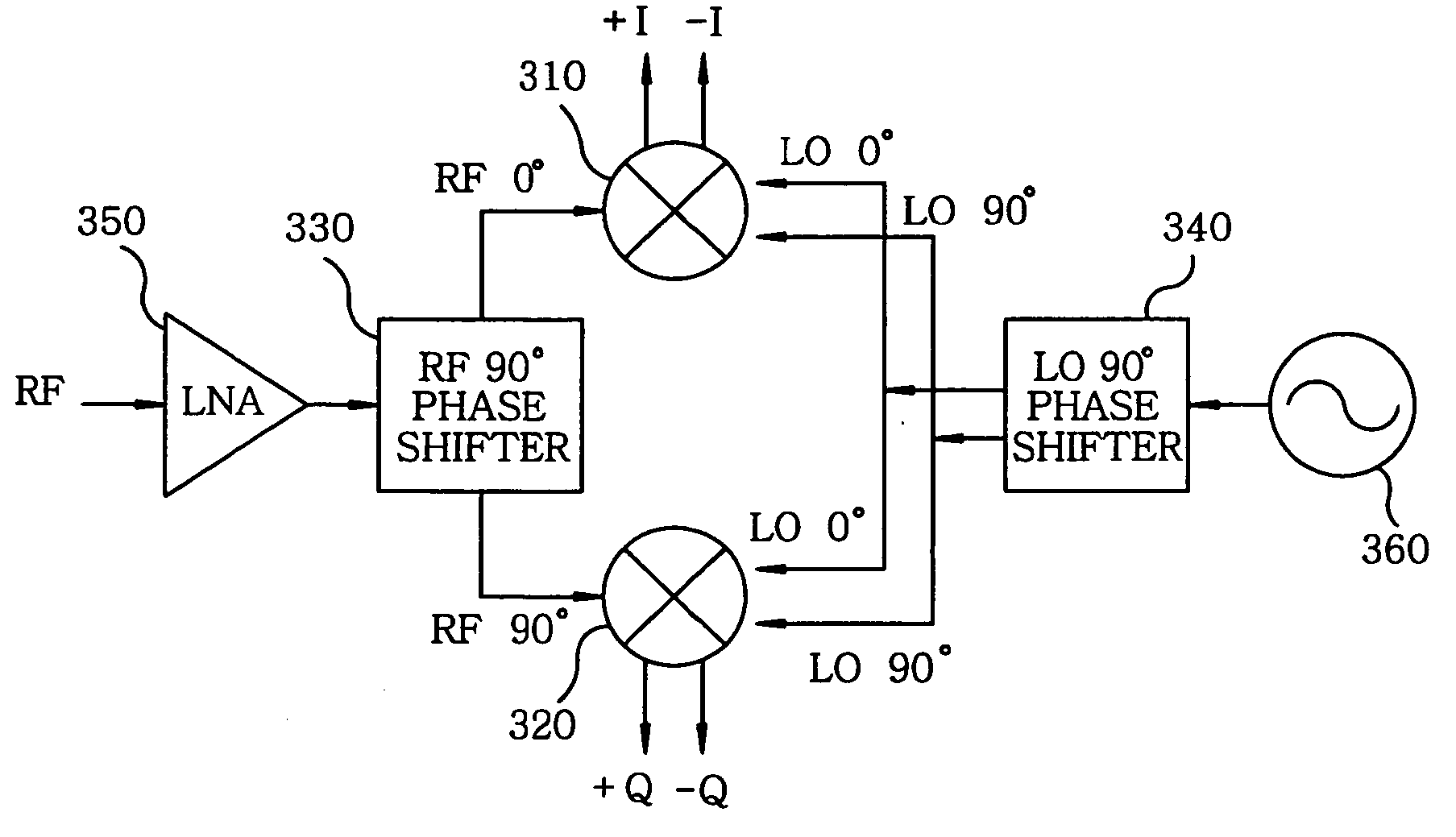
[0021] Referring to FIG. 3, there is shown a schematic configuration of a direct down-conversion receiver in accordance with the present invention. As shown therein, the direct-conversion receiver comprises an in-phase channel frequency mixer (hereinafter referred to as an I-channel frequency mixer) 310, a quadrature phase channel frequency mixer (hereinafter referred to as a Q-channel frequency mixer) 320, an RF 90° phase shifter 330, an LO 90° phase shifter 340, a Low Noise Amplifier (LNA) 350 and a Voltage Controlled Oscillator (VCO) 360.

[0022] First, an RF signal is received by an antenna (not shown) and is applied to the LNA 350. The RF signal is of a single-phase signal, not a differential signal. The LNA 350 amplifies the received RF signal while minimizing noise therein.

[0023] The output from the LNA 350 is then provided to the RF 90° ...


PUM


Abstract

Provided is a sub-harmonic frequency mixer having a structure in which two terminals of transistors receiving a Radio Frequency (RF) signal and a Local Oscillation (LO) signal are coupled. The frequency mixer is composed of a single-level structure of transistors and thus can be driven at a lower supply voltage compared to a common frequency mixer. A direct-conversion receiver employing such a frequency mixer needs an RF signal and an LO signal sources of single-phase. Therefore, the direct-conversion receiver has an architecture that simplifies a whole RF transceiver circuit and thus can be advantageously applied in implementing SoC (System-on-Chip) for a low power, high integration, low price and subminiature wireless transceiver circuit.

Description

FIELD OF THE INVENTION [0001] The present invention relates to a wireless reception unit and a sub-harmonic frequency mixer thereof, and more particularly, to a direct-conversion receiver and a direct-conversion frequency mixer thereof, which are capable of obtaining quadrature baseband signals by using a Local Oscillation (LO) signal and a Radio Frequency (RF) signal. BACKGROUND OF THE INVENTION [0002]FIG. 1 is a schematic configuration of a conventional direct-conversion receiver using a sub-harmonic frequency mixer. The direct-conversion receiver shown in FIG. 1 comprises a poly-phase filter 130, an LNA 150, an in-phase channel frequency mixer 110 and a quadrature phase channel frequency mixer 120. The poly-phase filter 130 generates LO signals for in-phase channels of 0°, 90°, 180° and 270°, and LO signals for quadrature channels of 45°, 135°, 225° and 315°. The LO signals for the in-phase channels generated by the poly-phase filter 130 are provided to the in-phase channel frequ...

Claims


Application Information

Patent Timeline
Patent Type & Authority Applications(United States)
IPC IPC(8): H04L27/22
CPCH04B1/30
Inventor CHOI, BYOUNG GUNPARK, CHUL SOONMYOUNG, NOGIL
Owner INFORMATION & COMMUNICATIIONS UNVERSITY EDUCATIONS UNIV EDUCATIONAL FOUNDATIION
Why Eureka
Try Eureka