
Power supply system and method for supplying power to a vehicle

a power supply system and vehicle technology, applied in the direction of emergency power supply arrangement, battery/fuel cell control arrangement, pulse technique, etc., can solve the problems of affecting the overall performance and fuel economy of the vehicle, affecting and thus the performance of the high voltage battery system. , to achieve the effect of reducing the possibility of overcharging the energy storage unit, reducing the impact of the weakest and strongest energy storage unit, and improving the effectiveness of the recondition

Active Publication Date: 2007-10-25
FORD GLOBAL TECH LLC
View PDF17 Cites 11 Cited by
  • Summary
  • Abstract
  • Description
  • Claims
  • Application Information

AI Technical Summary

Benefits of technology

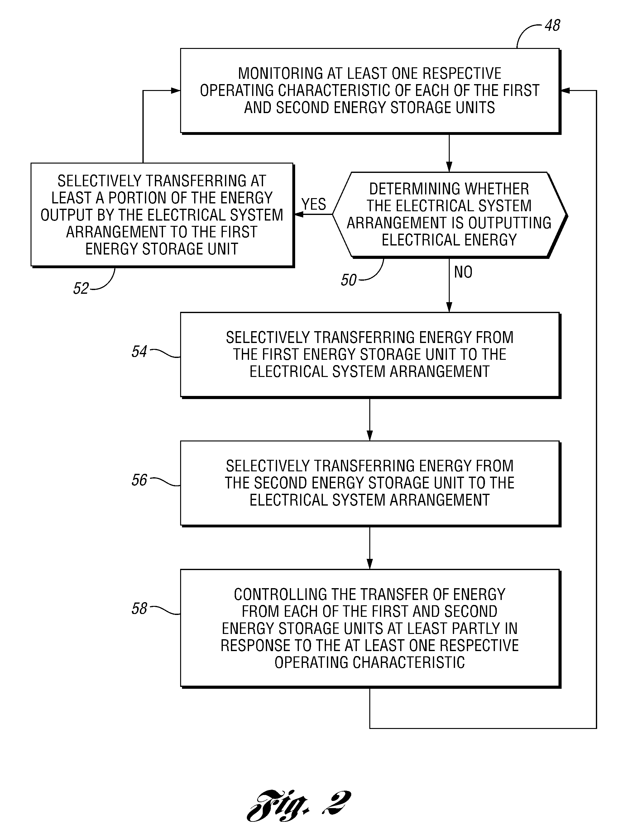
[0042] The method may include reducing the amount of energy selectively transferred from the first energy storage unit to the electrical system arrangement when the state of charge of the first energy storage unit does not meet the range of states of charge.
[0049] In an embodiment of the invention, independent control over each of the energy storage units, in response to energy storage unit temperature, allows the energy storage units to be placed in locations within the vehicle with different thermal characteristics.
[0050] In an embodiment of the invention, independent control over each of the energy storage units, in response to energy storage unit voltage or state of charge, allows the power supply system to efficiently use energy storage units of differing voltages, and consequently differing sizes.
[0051] In an embodiment of the invention, an energy storage unit can act as a “replacement unit” and be placed in a location within the vehicle that allows for easy replacement. This unit can be exposed to proportionately higher current levels compared to the other energy storage units. At these relatively higher current levels, the “replacement unit” would have a shorter life but the useful life of the other energy storage units would be extended.
[0055] In an embodiment of the invention, the power supply system includes a capacitor electrically connected to an electrical converter. During a power recharge event, e.g., during panic braking, the capacitor would capture current spikes generated by an electric machine that energy storage units would be unable to contain. This strategy captures regenerative energy while reducing the possibility of overcharging the energy storage units.
[0056] In an embodiment of the invention, the power supply system allows for a unique current to separately recondition each energy storage unit during vehicle operation. This procedure improves the effectiveness of the reconditioning process because it reduces the impact of the weakest and strongest energy storage units on the reconditioning process.

Problems solved by technology

Because of the battery and module series connections, the performance of a high voltage battery system is generally limited by the performance of the battery with the lowest voltage.
This voltage deviation may impact the performance of the high voltage battery system and thus impact overall vehicle performance and fuel economy.
Temperature deviations between batteries may also affect high voltage battery system performance and thus vehicle performance.
This strategy, however, may limit design and packaging options.
If a battery of a high voltage battery system becomes inoperable, the vehicle may be disabled or its performance may be significantly reduced until a replacement battery is installed.
Because of the battery and module series connections, the effectiveness of this reconditioning procedure is limited by, during discharge, the weakest battery, i.e., the battery with the lowest state of charge, and limited by, during charge, the strongest battery, i.e., the battery with the highest state of charge.
Reconditioning of a high voltage battery system cannot be performed while the vehicle is in operation.

Method used


Image

  • Power supply system and method for supplying power to a vehicle
  • Power supply system and method for supplying power to a vehicle
  • Power supply system and method for supplying power to a vehicle

Examples


Embodiment Construction

)

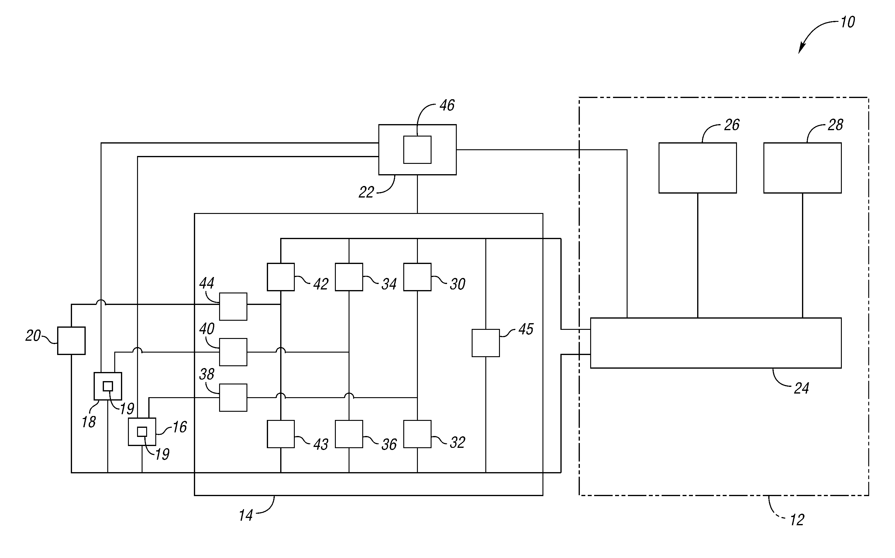
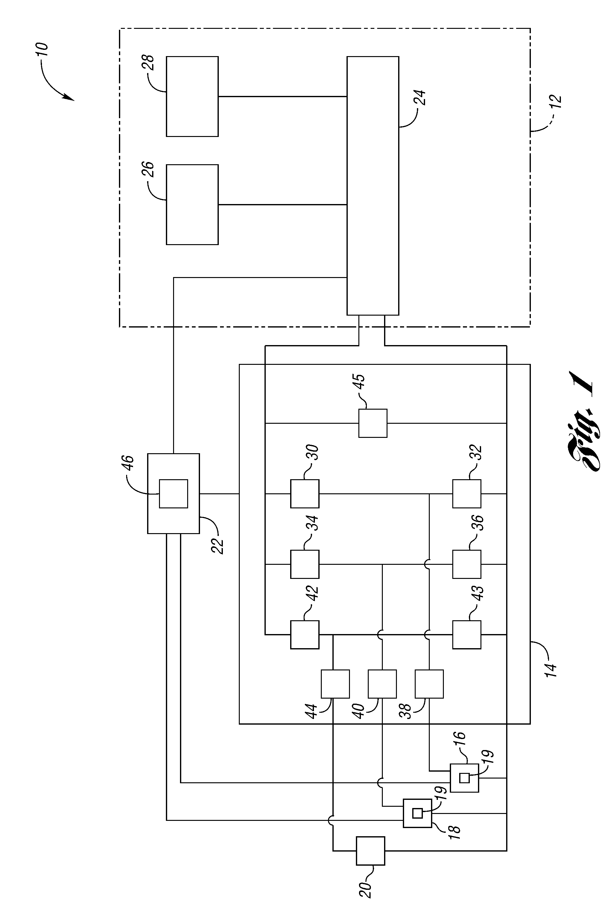
[0071]FIG. 1 shows a power supply system 10 for a vehicle (not shown). The power supply system 10 includes an electrical system arrangement 12, an electrical converter 14, first and second battery modules 16, 18, or energy storage units, a capacitor 20, and a control system 22.

[0072] The electrical system arrangement 12 includes an electrical bus 24, an electric load 26, and an electric machine 28, such as an electric motor. The electric machine 28 is capable of outputting electrical energy to the electrical bus 24.

[0073] The battery modules 16, 18 are each capable of receiving and storing electrical energy from the electrical converter 14. The battery modules 16, 18 are also capable of outputting electrical energy to the electrical converter 14.

[0074] In the embodiment of FIG. 1, there are two battery modules 16, 18. Any number of battery modules, however, may be used.

[0075] In the embodiment of FIG. 1, each of the battery modules 16, 18 contains a single battery cell 19. The ...


PUM


Abstract

A power supply system is provided that can operate with energy storage units of varying voltages and temperatures, that can correct voltage and temperature deviations, and that can continue to provide power when an energy storage unit is inoperable. A power supply system is also provided that can recondition an energy storage unit during vehicle operation.

Description

BACKGROUND OF THE INVENTION [0001] 1. Field of the Invention [0002] The invention generally relates to a system and method for supplying power to a vehicle. [0003] 2. Background Art [0004] Hybrid electric vehicles and fuel cell vehicles may use an electrical energy storage system to provide electrical energy to the vehicle and to capture electrical energy generated by the vehicle such as during a braking event. [0005] A high voltage battery system is an example of one such electrical energy storage system. A high voltage battery system can include a number of series connected energy storage units, or modules. Each module may contain one or more series connected energy storage cells, or batteries. [0006] Because of the battery and module series connections, the performance of a high voltage battery system is generally limited by the performance of the battery with the lowest voltage. As a result, the batteries used in a high voltage battery system are generally selected such that the...

Claims


Application Information

Patent Timeline
IPC IPC(8): B60L1/00B60L50/15
CPCB60L11/1851H02J7/1423H02J7/1438Y02T90/16Y02T10/7005Y02T10/705H02J7/345B60L58/10Y02T10/70B60L50/50H02J7/14H02J2207/20
Inventor ELDER, RONALDDEGNER, MICHAEL
Owner FORD GLOBAL TECH LLC
Learn More