Current detection device

a detection device and current technology, applied in the direction of automatic control, process and machine control, instruments, etc., can solve the problem of significant power attenuation of the method, and achieve the effect of reducing the number of parts, simplifying the circuit, and convenient mounting

Active Publication Date: 2007-10-25
VICTOR CO OF JAPAN LTD +1
View PDF6 Cites 97 Cited by
  • Summary
  • Abstract
  • Description
  • Claims
  • Application Information

AI Technical Summary

Benefits of technology

[0017]The current detection device of the present invention is composed of a pair of cores provided with an outer magnetic leg constituting a closed magnetic circuit on the choke coil and a center magnetic leg for providing a gap and an air core coil mounted on the center magnetic leg. And a space is provided to a part of winding of the air core coil so that the magnetic sensor can be easily mounted and placed in the gap between the space portion and the center magnetic leg. The magnetic sensor uses a Hall IC composed of a Hall element so that the number of parts can be reduced, circuits can be simplified and miniaturization and lower cost can be realized.
[0018]The

Problems solved by technology

This method has significant power attenuation because a current is constantly passed to the sensing resistor, which causes a seriou

Method used


Image

  • Current detection device
  • Current detection device
  • Current detection device

Examples


Embodiment Construction

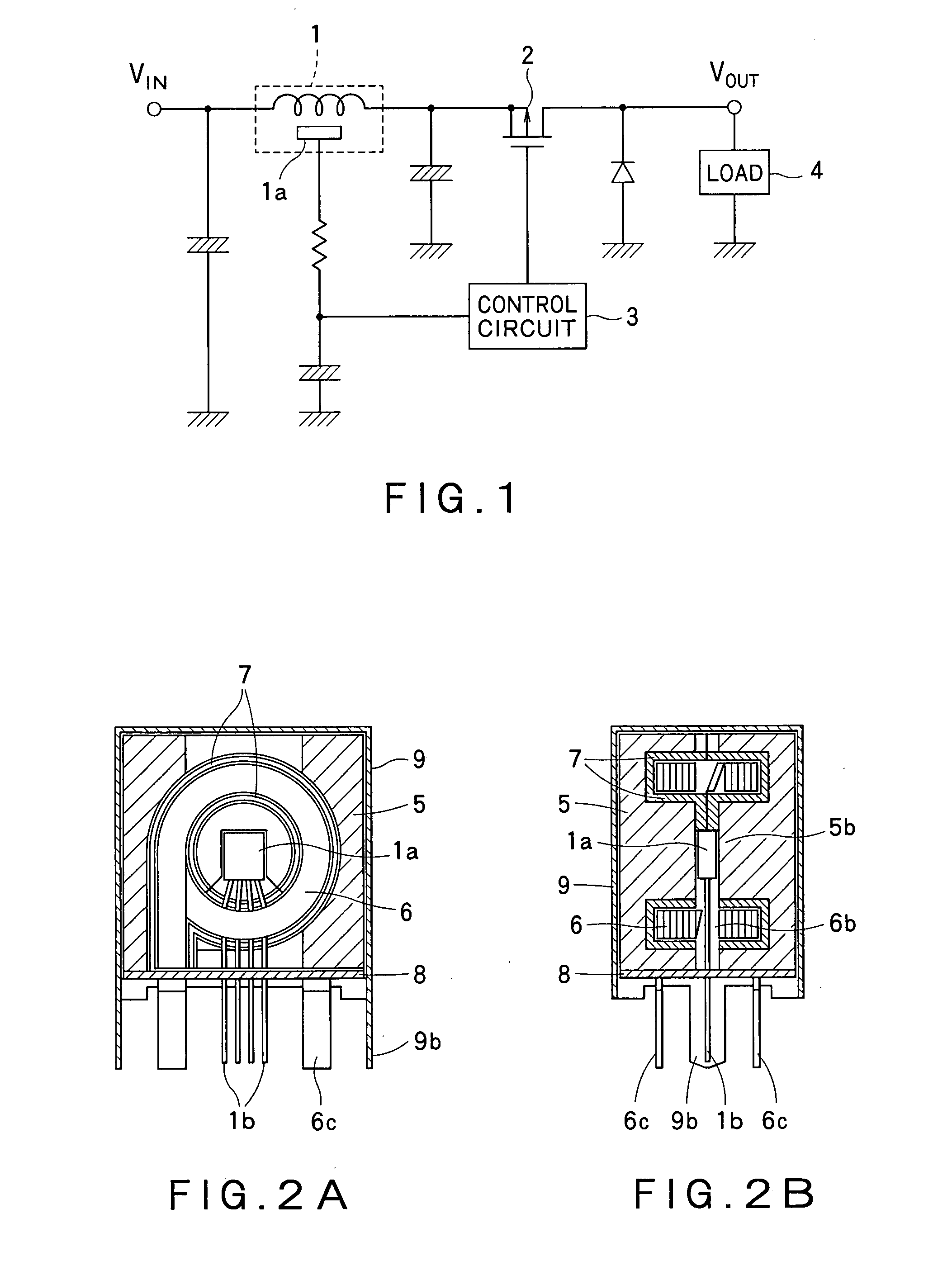
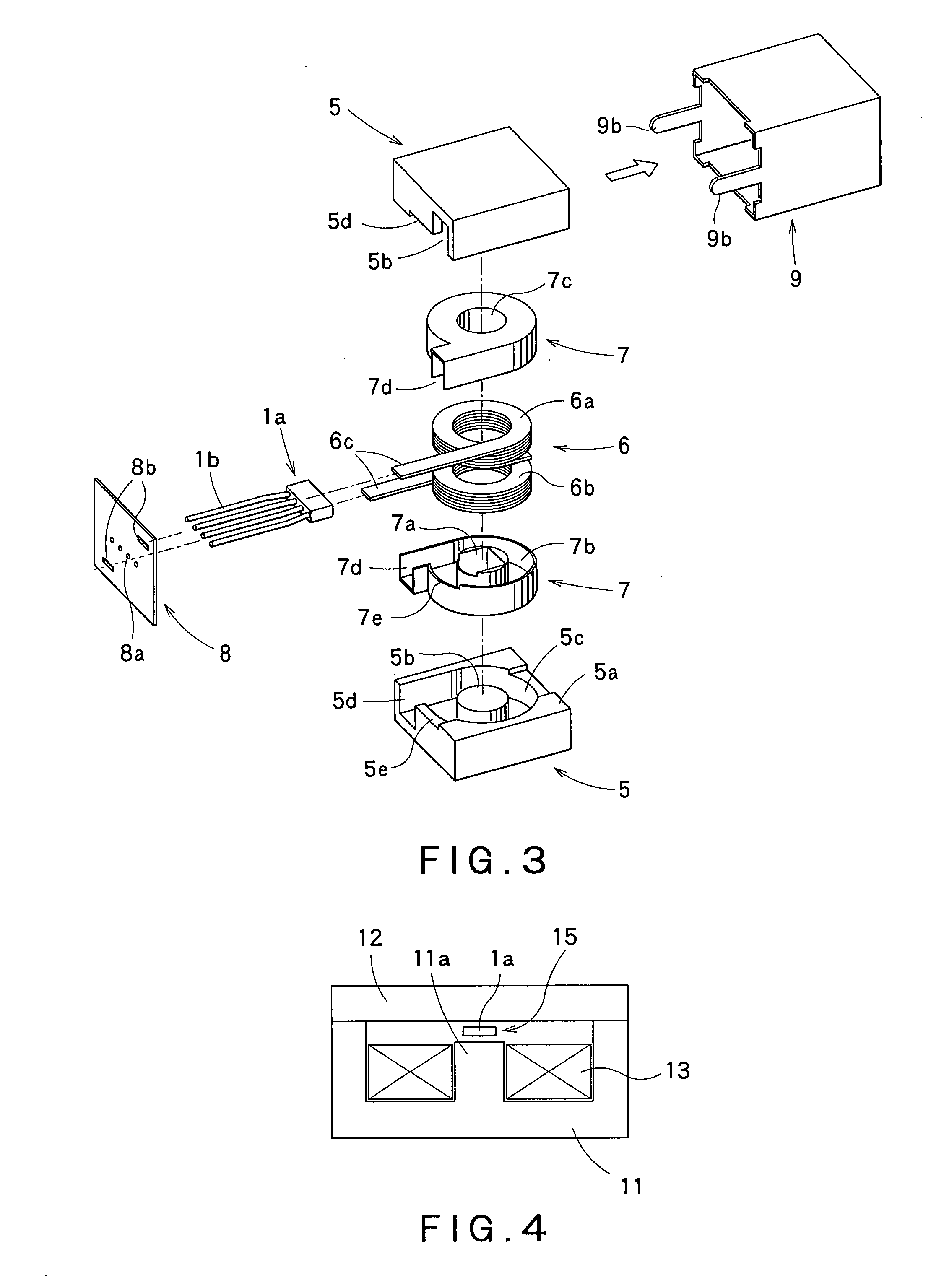
[0024]Hereafter, a current detection device according to the present invention will be described more specifically with reference to FIGS. 1 to 3.

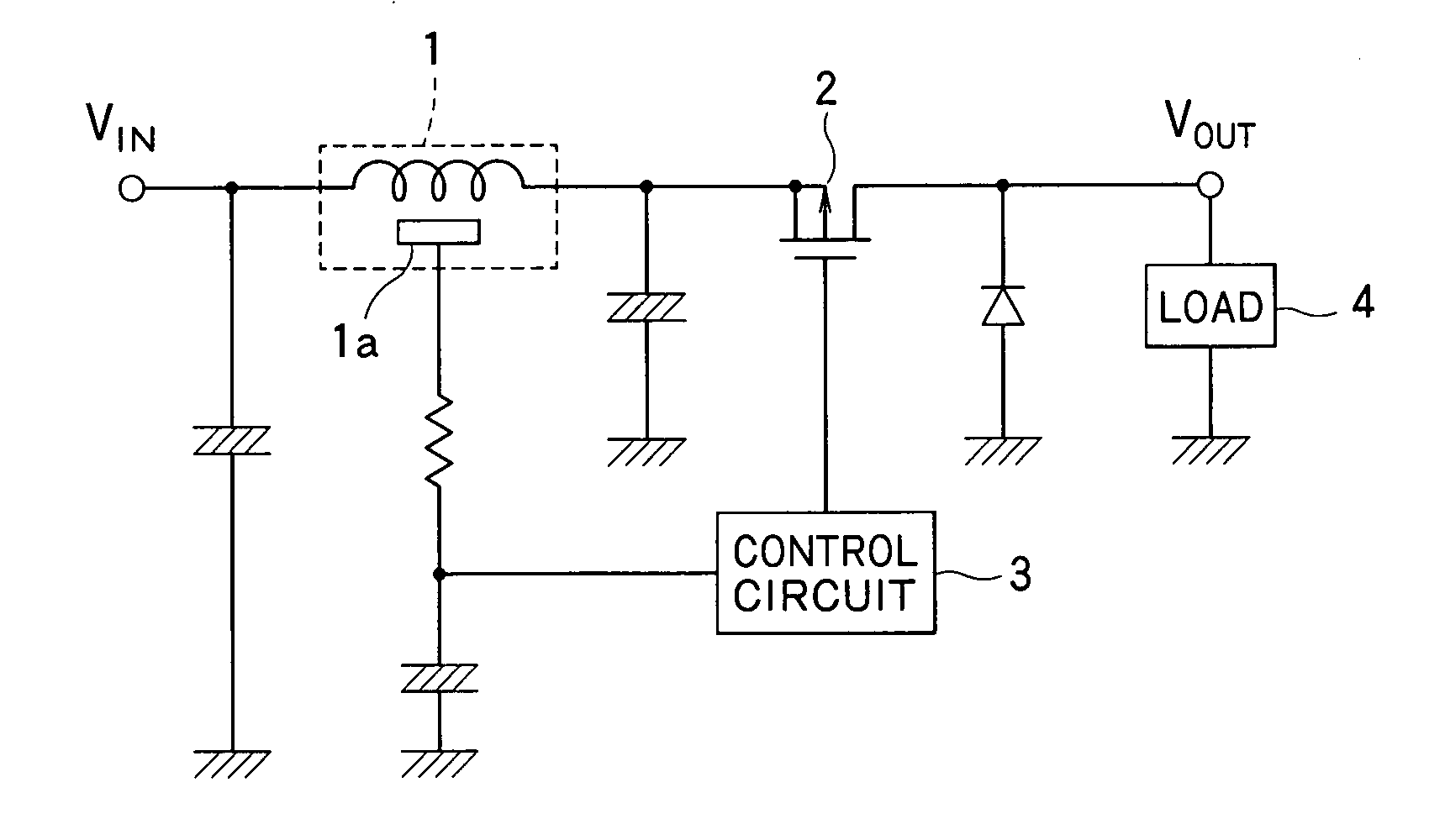
[0025]FIG. 1 shows a general current control circuit which uses a current detection device having a magnetic sensor built into a choke coil. In FIG. 1, reference numeral 1 denotes a current detection device having a magnetic sensor 1a built into a choke coil, 2 denotes a switching element, 3 denotes a control circuit, and 4 denotes a load such as a motor.

[0026]Thus, the current detection device having the magnetic sensor 1a built into the choke coil detects a magnetic flux generated by the current passing through the choke coil with the magnetic sensor 1a, and outputs a signal voltage proportional to the current to the control circuit by means of an additional circuit for voltage amplification or the like. The magnetic sensor 1a uses a Hall IC having a Hall element and another circuit such as an amplifier circuit incorporated therein so th...


PUM


Abstract

The present invention provides a low-cost current detection device having a magnetic sensor easily placed on a choke coil, wherein assembly and manufacturing costs are reduced and a product is miniaturized. A current detection device including a choke coil for smoothing an input current or an output current and a magnetic sensor 1a built into the choke coil to detect the input current or output current, wherein the choke coil is composed of: a pair of cores 5 provided with an outer magnetic leg 5a constituting a closed magnetic circuit and a center magnetic leg 5b for providing a gap; and an air core coil 6 mounted on the center magnetic leg 5b, and space 6b is provided to a part of winding of the air core coil 6 with the magnetic sensor 1a placed in the gap between the space 6b and the center magnetic leg 5b.

Description

BACKGROUND OF THE INVENTION[0001]1. Field of the Invention[0002]The present invention relates to a current detection device, and in particular, to a current detection device having a magnetic sensor built into a choke coil.[0003]2. Related Art[0004]A current control device generally feeds back a detection signal obtained from a detection circuit to a control circuit for the sake of stabilization by means of a detection circuit having a sensing resistor for detecting a current or voltage connected in series with a load on an output side thereof in order to exert constant voltage and constant current control. This method has significant power attenuation because a current is constantly passed to the sensing resistor, which causes a serious problem to a power circuit for passing a high current, such as a resistance change due to heat generation of the sensing resistor.[0005]As means for solving this problem, there is a current detection device conventionally known, which is provided wi...

Claims


Application Information

Patent Timeline
IPC IPC(8): G05F1/24
CPCG01R15/207G01R15/202
Inventor KOGA, AKIHIRO
Owner VICTOR CO OF JAPAN LTD
Why Eureka
Try Eureka