Batch-fabricated, rf-interrogated, end transition, chip-scale atomic clock

a chip-scale, atomic clock technology, applied in the field of atomic clocks, can solve the problems of reducing the effectiveness of end-transition cpt techniques, limiting clock dimensions, and limiting performance/applications, and achieve the effect of improving signal-to-nois

Inactive Publication Date: 2007-10-25
SRI INTERNATIONAL
View PDF5 Cites 94 Cited by
  • Summary
  • Abstract
  • Description
  • Claims
  • Application Information

AI Technical Summary

Benefits of technology

[0015]A number of feedback loops can apply and detect signals to and from the coils and laser source. A first feedback loop maintains a local-oscillator frequency of the RF interrogation signal of about 9.19 GHz (cesium) by applying RF power with FM dither to the RF excitation coils and detecting from the photodetector a demodulated dithering signal of about 2.9 KHz. An atomic clock time base of about 10 MHz is derived from this feedback loop in a conventional way. A second feedback loop derives the drive frequency from the first clock loop, and maintains a frequency of a Zeeman interrogation signal of about 30 KHz, by applying to the Zeeman interrogation coils power of such a frequency (determined by the value of the magnetical...

Problems solved by technology

Limitations of conventional atomic clocks include the use of microwave cavities which limit the clock dimensions as well as place a limit on performance/applications...

Method used


Image

  • Batch-fabricated, rf-interrogated, end transition, chip-scale atomic clock
  • Batch-fabricated, rf-interrogated, end transition, chip-scale atomic clock
  • Batch-fabricated, rf-interrogated, end transition, chip-scale atomic clock

Examples


Embodiment Construction

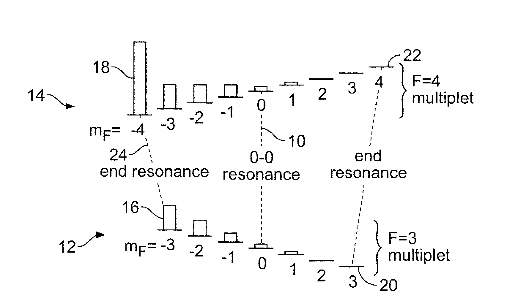
[0033]FIG. 1 depicts the transition states of the atoms of an atomic clock vapor in the presence of magnetic fields. (For the present discussion, the atomic vapor can be made of cesium atoms, but the technique described below is applicable to any alkali element). The 0-0 transition (resonance) 10 is exhibited after the Zeeman sublevels are split in an external magnetic field. With no magnetic field applied, all the Zeeman sublevels occupy the same energy levels of the 0-0 transition 10. Applying a DC magnetic field causes the states 12, 14 to separate into a number of lower 12 and upper 14 Zeeman transition states at different energy levels. The states with the minimum difference in energy 16, 18, or left end resonance, and the maximum difference in energy 20, 22, or right end resonance, are called the end states (resonances).

[0034]The desired end-transition states for use in the present invention are the minimum end states (resonance) 16, 18 or maximum state. An optical vertical ca...


PUM


Abstract

A chip scale atomic clock is disclosed that provides a low power atomic time/frequency reference that employs direct RF-interrogation on an end-state transition. The atomic time/frequency reference includes an alkali vapor cell containing alkali atoms, preferably cesium atoms, flex circuits for physically supporting, heating, and thermally isolating the alkali vapor cell, a laser source for pumping alkali atoms within the alkali vapor cell into an end resonance state by applying an optical signal along a first axis, a photodetector for detecting a second optical signal emanating from the alkali vapor cell along the first axis, a pair of RF excitation coils for applying an RF-interrogation signal to the alkali atoms along a second axis perpendicular to the first axis, a pair of bias coils for applying a uniform DC magnetic field along the first axis, and a pair of Zeeman coils for applying a Zeeman interrogation signal to the alkali atoms and oriented and configured to apply a time-varying magnetic field along the second axis through the alkali vapor cell. Another flex circuit is used for physically supporting the laser source, for heating the laser source, and for providing thermal isolation of the laser source. The laser source can be a vertical cavity surface emitting laser (VSCEL). The bias coils can be Helmholtz coils.

Description

CROSS-REFERENCE TO RELATED APPLICATIONS[0001]This application claims the benefit of U.S. provisional patent application No. 60 / 793,171 filed Apr. 19, 2006, the disclosure of which is incorporated herein by reference in its entirety.GOVERNMENT RIGHTS IN THIS INVENTION[0002]This invention was made with U.S. government support under contract number NBCHC020045. The U.S. government has certain rights in this invention.FIELD OF THE INVENTION[0003]The present invention relates generally to atomic clock, and more particularly to an atomic clock that operates by means of radio frequency (RF) interrogation operating on an end-transition state of an atomic vapor.BACKGROUND OF THE INVENTION[0004]Atomic clocks have been used in systems that require a very accurate time base or frequency measurement. Typical applications include global positioning systems (GPS) satellites, cellular phone systems, scientific experiments, and military applications. Conventional atomic clocks operate by use of an o...

Claims


Application Information

Patent Timeline
IPC IPC(8): H01S1/06
CPCH01S5/141G04F5/14
Inventor BRAUN, ALAN MICHAELABELES, JOSEPH HYCHAN, WINSTON KONGKWAKERNAAK, MARTINDAVIS, TIMOTHY JAMES
Owner SRI INTERNATIONAL
Why Eureka
Try Eureka