Projection illumination systems lenses with diffractive optical elements

a technology of diffractive optical elements and projection display, which is applied in the field of projection display, can solve the problems of chromatic aberration, heavy weight of aspherical glass lenses, and high cost of fabrication, and achieves the effect of easy manufacturing and light weigh

Inactive Publication Date: 2007-10-25
OC OERLIKON BALZERS AG
View PDF11 Cites 3 Cited by
  • Summary
  • Abstract
  • Description
  • Claims
  • Application Information

AI Technical Summary

Benefits of technology

[0019] Such lenses could be realized with plastic substrates. They are thin and light weight, and easy to manufacture.

Problems solved by technology

First, the aspherical glass lenses are heavy and bulky, and expensive to fabricate.
Second, such systems are prone to chromatic aberrations, because the lenses have different focal lengths for different wavelengths of the light.
Unfortunately such fresnel lenses exhibit the effect of chromatic aberrations.
Diffraction occurs when two or more spatially separated beams are coherently combined and interfere either constructively or destructively.

Method used


Image

  • Projection illumination systems lenses with diffractive optical elements
  • Projection illumination systems lenses with diffractive optical elements
  • Projection illumination systems lenses with diffractive optical elements

Examples


first embodiment

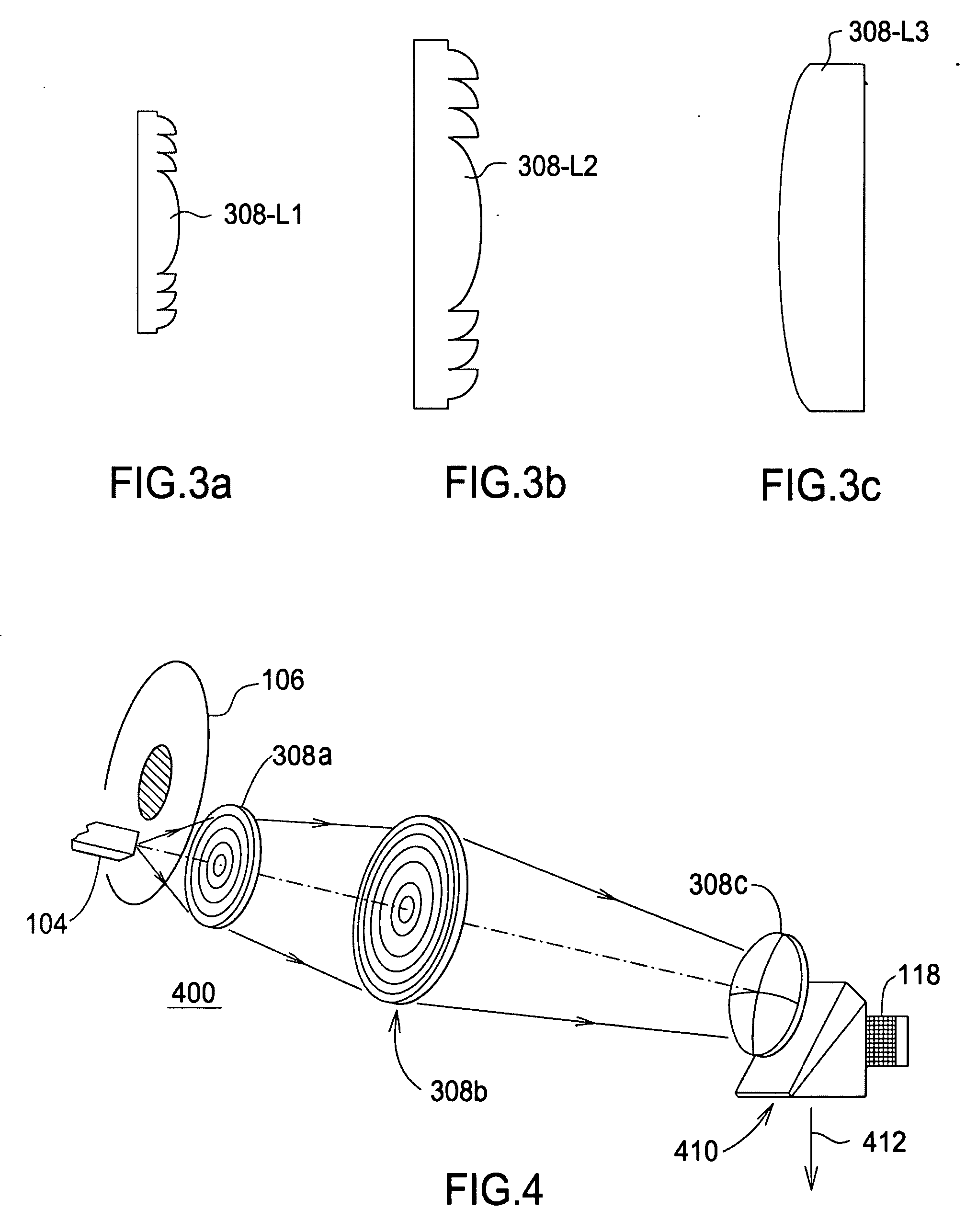
[0028]FIG. 3 is a side view of lenses 308-L1, 308-L2, and 308-L3 forming the illumination system optics according to the present invention. In this particular embodiment, lens 308-L1 is a refractive fresnel lens and lens 308-L2 is a lens which comprises a refractive as well as a diffractive fresnel lens, while lens 308-L3 is a conventional refractive lens. FIG. 3 does not show that lens 308-L2 includes a surface with a diffractive fresnel lens used to correct for chromatic aberrations. This is shown in FIGS. 6-8. In the example of FIGS. 6-8 the diffractive fresnel lens is a kinoform. This combination has been shown to work well, but many variations are possible. For example, all three lenses could comprise refractive fresnel lenses (or conventional lenses). More than one of the lenses could include such a diffractive optical element.

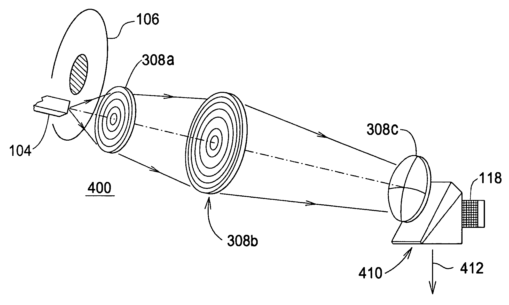
[0029]FIG. 4 is a side isometric view of a projection system 400 utilizing the illumination system optics of FIG. 3. This system is somewhat similar to ...

second embodiment

[0038]FIGS. 7A and B show lens 308-L1. Again, FIG. 7B is blown up from a portion of FIG. 7A, and greatly exaggerated for detail. This embodiment is similar to that of FIGS. 6A and 6B, except that the kinoforms are formed on top of the fresnel structure.

[0039] A prototype version of this embodiment was fabricated by diamond turning the plastic lens on a special lathe which carved the plastic. In commercial fabrication, a similar process could be used, but to form a mold which would then be used to form the lenses.

third embodiment

[0040]FIGS. 8A and 8B show a third embodiment, which is a variation of lens 308-L1. Again, FIG. 8B is blown up from a portion of FIG. 8A, and greatly exaggerated for detail. The embodiment of FIGS. 8A and 8B is based on a conventional lens, rather than a fresnel lens, and has the kinoforms formed on the curved surface of the lens. As an alternative, kinoforms could be formed on a flat surface of a conventional lens having a flat surface.

[0041] The embodiment of FIGS. 8A and 8B sacrifices the light weight and size of a fresnel lens, but maintains the color performance provided by the kinoforms. Hence it is useful in some configurations.

[0042] It will be appreciated by one versed in the art that there are many possible variations on these designs. Some known and anticipated variations are described below:

[0043] Any lens which results in the desired diffraction as produced by the specific embodiments described above is encompassed within the present invention. The specific embodiment...


PUM


Abstract

An optical assembly for a projection illumination system has a refractive lenses and a diffractive lens for imaging a sheet of light from a light source onto a Spatial Light Modulator (SLM). One embodiment utilizes a fresnel lens having kinoforms formed on a surface. Such a lens may be molded using a light-weight plastic in a single step.

Description

BACKGROUND OF THE INVENTION [0001] 1. Field of the Invention [0002] This invention relates to illumination systems utilizing diffraction pattern-forming lenses. In particular, this invention relates to illumination systems in projection displays wherein lenses based on refraction at least partially have been replaced with diffractive optical elements. [0003] 2. Description of Related Art [0004]FIG. 1 (Prior Art) shows a conventional projection display 100. Such a system may be used for a front or rear projection system or the like. An example of a well known application is the television. [0005] Lamp 102 provides light which is integrated by integrator 104. Integrator 104 is, for example, a hollow path formed by four inward facing mirrors. Light from lamp 102 bounces off the mirrors many times, so that a uniform rectangular field of light is formed at the exit of integrator 104. Color filters 106 are designed to provide the correct color of light when Spatial Light Modulator (SLM) 1...

Claims


Application Information

Patent Timeline
Patent Type & Authority Applications(United States)
IPC IPC(8): G02B5/18
CPCG02B3/08G02B5/1895G02B5/1876
Inventor FRANCIS, MELVIN
Owner OC OERLIKON BALZERS AG
Why Eureka
Try Eureka