Air driven pump with performance control

a technology of performance control and air driven pump, which is applied in the direction of flexible member pump, machine/engine, positive displacement liquid engine, etc., can solve the problems of pump operation finding maximum flow limit, pump efficiency decline, and inability to address both efficient operation and variation in demands placed on the pump. , to achieve the effect of varying the pump efficiency

Active Publication Date: 2007-10-25
PSG CALIFORNIA LLC
View PDF11 Cites 20 Cited by
  • Summary
  • Abstract
  • Description
  • Claims
  • Application Information

AI Technical Summary

Benefits of technology

[0009] The present invention is directed to air driven pumps using an actuator having a reciprocating air valve with opposed air chambers. The actuator includes an intake to the air valve having an intake passage and an adjuster controlling flow through the intake passage. The adjuster includes a closure element which adjustably extends into the intake passage to the air valve. Employment of the intake adjuster allows a balancing of pump flow with varying pump efficiency.
[0010] Through restriction, the charge of air on the pumping stroke can be reduced under light and moderate pumping loads. This lessens the demand on the exhaust side as less accumulated pressure must be released. Further, pumping can be achieved with less build up of pressure when full pressure cannot deliver a proportionally greater flow, typically due to pumped material flow constraints, or when full flow is not needed. Efficient reduction in power requirements is achieved by reducing the driving air pressure within the air chambers rather than through back pressure imposed on the pumped material or powering air.
[0011] In a first separate aspect of the present invention, the adjuster is located in the actuator housing to provide predictable performance adjustments on the air valve and associated pump.
[0012] In a second separate aspect of the present invention, a nonlinear control on the actuator is provided. At low airflow rates, intake adjuster position becomes proportionally more sensitive. The nonlinear control can also be configured to make changes in air consumption by the actuator substantially directly proportional to the settings of the actuator.

Problems solved by technology

Actuators for air driven pumps commonly include an air valve which controls flow to alternate pressure and exhaust to and from each of the air chambers, resulting in reciprocation of the pump.
Consequently, pump operation finds maximum flow limited by such things as suction and pressure head and fluid flow resistance.
It remains that control of either the output of the pump or the exhaust of the actuator can alter the performance of the pump to achieve desired flow rates below the maximum but such control does not address both efficient operation and variation in demands placed on the pump.

Method used


Image

  • Air driven pump with performance control
  • Air driven pump with performance control
  • Air driven pump with performance control

Examples


Embodiment Construction

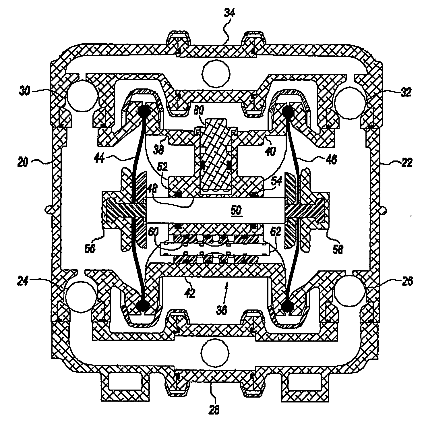
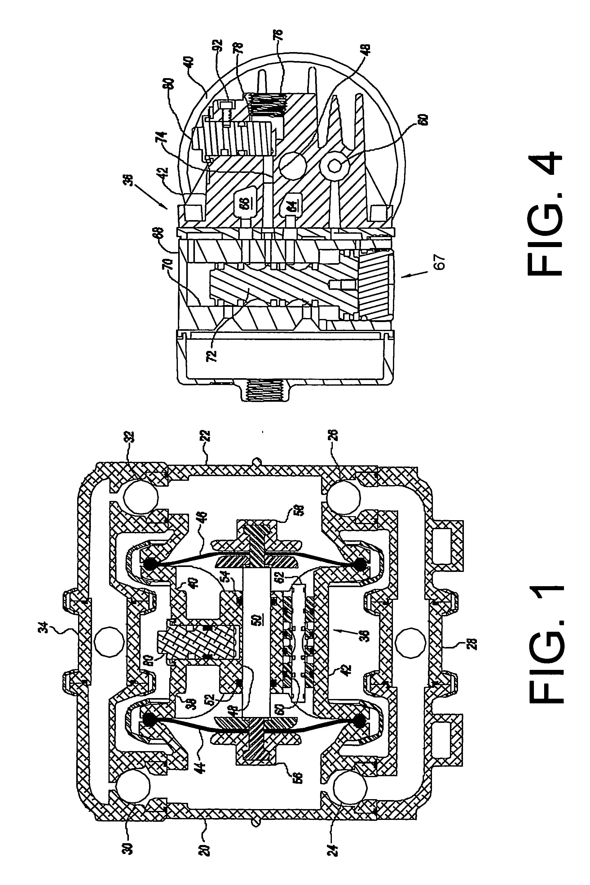
[0023] Turning in detail to the Figures, an air driven double diaphragm pump is illustrated in FIG. 1. The principles applicable to the pump construction and operation contemplated in this preferred embodiment are fully described in U.S. Pat. No. 5,957,670, the disclosure of which is incorporated herein by reference.

[0024] The pump structure includes two pump chamber housings, 20, 22. These pump chamber housings 20, 22 each include a concave inner side forming pumping cavities through which the pumped material passes. One-way ball valves 24, 26 are at the lower end of the pump chamber housings 20, 22, respectively. An inlet manifold 28 distributes material to be pumped to both of the one-way ball valves 24, 26. One-way ball valves 30, 32 are positioned above the pump chamber housings 20, 22, respectively, and configured to provide one-way flow in the same direction as the valves 24, 26. An outlet manifold 34 is associated with the one-way ball valves 30, 32.

[0025] Inwardly of the ...


PUM


Abstract

An air driven diaphragm pump includes an performance control actuator having a housing with opposed air chambers. The pump includes pump chambers facing the air chambers and pump diaphragms extending between each air chamber and each pump chamber, respectively. The actuator further includes an air valve, an intake to the air valve and an engagement. The intake includes an intake passage and a performance control intake adjuster rotatably mounted. The intake adjuster has a helical channel and a closure element extending adjustably into the intake passage. The engagement engages the helical channel for control of the intake. The helical channel has varied pitch to provide a nonlinear relationship between rotation and axial advancement of the intake adjuster. The nonlinear relationship gives flow rate proportional to the angular rotation of the intake adjuster. The end points of the channel provide a practical minimum pump performance of about 40% of maximum pump flow rate and a maximum pump performance of about 97% of maximum pump flow rate.

Description

BACKGROUND OF THE INVENTION [0001] The field of the present invention is pumps and actuators for pumps which are air driven. [0002] Pumps having double diaphragms driven by compressed air directed through an actuator valve are well known. Reference is made to U.S. Pat. Nos. 5,957,670; 5,213,485; 5,169,296; and 4,247,264; and to U.S. Pat. Nos. Des. 294,947; 294,946; and 275,858. These air driven diaphragm pumps employ actuators using feedback control systems which provide reciprocating compressed air for driving the pumps. Reference is made to U.S. Patent Application Pub. No. 2005 / 0249612 and to U.S. Pat. No. 4,549,467. Another mechanism to drive an actuator by solenoid is disclosed in U.S. Pat. No. RE 38,239. The disclosures of the foregoing patents and patent application publication are incorporated herein by reference. [0003] Other pumps may be driven by the same actuators but use other arrangements of operatively opposed air actuating chambers to drive a reciprocating pumping mec...

Claims


Application Information

Patent Timeline
Patent Type & Authority Applications(United States)
IPC IPC(8): F04B43/06
CPCF04B43/0736Y10T137/8275
Inventor DIETZSCH, CURTIS W.DUNCAN, GREG S.LENT, GARY K.
Owner PSG CALIFORNIA LLC
Why Eureka
Try Eureka